Q200 AC/DC Quattro Charger SkyRC Technology Co., Ltd. 2016 Version 1.
TABLE OF CONTENTS INTRODUCTION 01 SPECIAL FEATURES 03 WARNING AND SAFETY NOTES 06 PROGRAM FLOW CHART 09 OPERATION 10 OPERATING PROGRAM 11 CHARGING PROGRAM 16 BATTERY MEMORY SET AND CALL OUT 17 SYSTEM SETTING 19 BATTERY METER 21 BATTERY RESISTANCE METER 22 WARNING AND ERROR MESSAGE 23 USING THE CHARGE CONTROL SOFTWARE “CHARGE MASTER” 24 SPECIFICATION 25 CONFORMITY DECLARATION 26 COMMONLY USED TERMS 27 WARRANTY AND SERVICE 28
INTRODUCTION Congratulations on your choice of SKYRC Q200 AC/DC Quattro Balance Charger/Discharger. This unit is simple to use, but the operation of a sophisticated automatic charger such as SKYRC Q200 does require some knowledge on the part of the user. These operating instructions are designed to ensure that you quickly become familiar with its functions.
INTRODUCTION Please read this entire operating manual completely and attentively before using this product, as it covers a wide range of information on operating and safety.
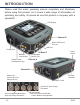
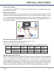
SPECIAL FEATURES Colorful LCD Display It is equipped with 480*320 3.5" colorful LCD display. The user interface looks clear, visible and comfortable. Four-channel Charger SKYRC Q200 allows you to plug 4 batteries into one charger simultaneously, and it will intelligently and automatically charge 4 battries at once to their maximum capacity. To top of it, the batteries being charged do not even need to have the same configuration.
SPECIAL FEATURES Battery Memory (Data Store/Load) The charger can store up to 40 different charge/discharge profiles for each channel. You can keep the data pertaining to program setting of the battery of continuous charging or discharging. Users can call out these data at any time without any special program setting. Charge/Discharge Indication There is a clear icon when the charger is in process to indicate and charge or discharge status and the current capacity percentage.
SPECIAL FEATURES Fast and Storage Mode of Lithium Battery Purposes to charge lithium battery varies, 'fast' charge reduce the duration of charging, whereas 'store' state can control the final voltage of your battery, so as to store for a long time and protect useful time of the battery. Re-Peak Mode of NiMH/NiCd Battery In re-peak charge mode, the charger can peak charge the battery once, twice or three times in a row automatically. This is good for making certain the battery is fully charged.
WARNING AND SAFETY NOTES These warnings and safety notes are particularly important. Please follow the instructions for maximum safety; otherwise the charger and the battery can be damaged or at worst it can cause a fire. Never leave the charger unattended when it is connected to its power supply. If any malfunction is found, TERMINATE THE PROCESS AT ONCE and refer to the operation manual. Keep the charger well away from dust, damp, rain, heat, direct sunshine and vibration. Never drop it.
WARNING AND SAFETY NOTES Never attempt to charge or discharge the following types of batteries. A battery pack which consists of different types of cells (including different manufacturers) A battery that is already fully charged or just slightly discharged. Non-rechargeable batteries (Explosion hazard). Batteries that require a different charge technique from NiCd, NiMh, LiPo or Gel cell (Pb, Lead acid). A faulty or damaged battery. A battery fitted with an integral charge circuit or a protection circuit.
WARNING AND SAFETY NOTES Please get highlighted that lithium battery packs can be wired in parallel and in series. In the parallel connection, the battery s capacity is calculated by multiplying single battery capacity by the number of cells with total voltage stay the same. The voltages imbalance may cause fire or explosion .Lithium battery is recommended to charge in series.
PROGRAM FLOW CHART Note: The flow chart is taking one channel for example as the flow chart for the two channels (Channel A, B, C and Channel D) are identical. INC DEC START LiPo BALANCE CHG INC LiPo CHARGE BATT/PROGRAM 7.4V (2S) LiPo BATT ENTER 2.0A 7.4V (2S) DEC 2.0A INC DEC LiPo FAST CHARGE 2.0A 7.4V (2S) INC DEC INC LiPo DISCHARGE LiPo STORAGE 2.0A 7.4V (2S) DEC 2.0A 7.4V (2S) INC DEC START LiFe BALANCE CHG BATT/PROGRAM LiFe BATT ENTER 2.0A 6.6V (2S) INC LiFe CHARGE DEC 2.0A 6.
OPERATION CHANNEL A/B/C/D It is used to switch among channels. BATT PROG / STOP Button: It is used to stop the progress or go back to previous step/screen DEC Button: It is used to go through the menus and decrease the parameter value INC Button: It is used to go through the menus and increase the parameter value ENTER / START Button: It is used to enter parameter or store parameter on screen.
OPERATING PROGRAM Here is the detailed procedure to make the charger work. All the screens and operations will take Li-Po BALANCE CHARGE program for example, Note: We will explain one channel as the operating procedure of Channel A, B, C and D is identical. 1. Connection 1). Connecting to power source There are two kinds of inputs for SKYRC Q200, DC 11-18V and AC 100-240V. A. Operating in AC mode SKYRC Q200 comes with built in switching power supply.
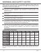
OPERATING PROGRAM Please refer to below table for detailed distributed power value in different channels. CH A CH B CH C CH D Charging Power 0-100W 50-100W 0-100W 50-100W 0-50W 0-50W 0-50W 0-50W Power Distribution A+C=100W B+D=100W A+C=100W DC Mode Charging Power AC Mode B+D=100W Note 1: The total power of Channel A and Channel C is 100W; and the total power of Channel B and Channel D is 100W. Note 2: Power distribution can be applied in certain two channels.
OPERATING PROGRAM 2). Connecting the battery Important!!! Before connecting a battery it is absolutely essential to check one last time that you have set the parameters correctly. If the settings are incorrect, the battery may be damaged, and could even burst into flames or explode. To avoid short circuits between the banana plugs, always connect the charge leads to the charger first, and only then to the battery. Reverse the sequence when disconnecting the pack. 3).
OPERATING PROGRAM 2. Getting started Locate the flowcharts show the entire programming menu. It is highly recommended to have these flowcharts handy while learning to operate this charger. There are two main ways in which to set the charger. (1) A memory profile is available for setting and storing pertinent information for up to 40 different batteries, each channel can store 10 sets. Once a battery's information is stored into a memory it will be retained until changed again manually.
OPERATING PROGRAM R:3SER S:3SER CONFIRM(ENTER) START/ENTER R shows the number of cells detected by the charger and S is the number of cells set by you at the previous screen. If both numbers are identical, press START/ENTER to start charging process. 7. Charging Status Monitor Lp4s 1.5A 12.14V During charge process, real-time status will be showed as left screen. NOTE: The battery icon indicates the charge / discharge status and finished capacity percentage.
OPERATING PROGRAM 8. Program Stop During the charging process, press STOP to stop the charging process. 9. Program Complete When the charging process finishes, an audible sound will be heard. Charging Program Depends on different battery types, the operation programs are different. Batt Type LiPo Lilon LiFe LiHV NiMH NiCd Pb · 16 Operation Program Description CHARGE This charging mode is for charging LiPo/LiFe/LiIon/LiHV battery in normal mode.
BATTERY MEMORY SET AND CALL OUT The charger can store up to 40 different charge/discharge profiles(each channel 10 sets) for your convenience, and the stored profiles can be recalled quickly without having to go through the setup process. When you are willing to alter the parameter value in the program, press START/ENTER to make it blink then change the value with INC or DEC. The value will be stored by pressing START/ENTER once. Note: All following screen are taking 2S(7.4V) LiPo battery for example. 1.
BATTERY MEMORY SET AND CALL OUT SAVE PROGRAM SAVE…. [ BATT MEMORY 1 ] LiPo 7.4V (2S) [ BATT MEMORY 1 ] C:4.9A D:2.2A START/ENTER >3 Seconds ENTER CHARGER LOAD…… LiPo BALANCE CHG 4.9A · 18 7.4V(2S) Indicate the battery type and battery cell of the saved profile. Indicate the charge and discharge current of the saved profile. Press the START/ENTER for 3 seconds to call out the memory. 2. Battery Memory Call Out Load the memory set Press START/ENTER for 3 seconds to start the process.
SYSTEM SETTING It will be operated with the default value of the essential user settings when it is powered on for the first time.The screen displays the following information in sequence and the user can change the value of parameter on each screen. When you are willing to alter the parameter value in the program, press START/ENTER to make it blink then change the value with INC or DEC. The value will be stored by pressing START/ENTER once.
SYSTEM SETTING SELECTION ITEM DESCRIPTION NiMH Sensitivity Default: 4mV/Cell 5-15mV/Cell This program is for NiMH/NiCd battery only. When the charger detects the delta peak value reaches the value you set, the charger will say the battery is fully charged. OFF/ON The beep sounds at every time touching the buttons to confirm your action. The beep or melody sounded at various times during operation to alert different mode changes. 10.0-11.0V This program monitors the voltage of input battery.
BATTERY METER The user can check battery's total voltage, the highest voltage, the lowest voltage and each cell's voltage. Please connect the battery to the charger main battery lead to battery socket and balance wires to balance socket. Battery Pack A 4.19 4.15 4.15 4.19 4.18V 4.18V B 4.19 4.15 4.15 4.19 4.18V 4.18V C 4.19 4.15 4.15 4.19 4.18V 4.18V D 4.19 4.15 4.15 4.19 4.18V 4.
BATTERY RESISTANCE METER The user can check battery's total resistance, the highest resistance, the lowest resistance and each cell's resistance. Please connect the battery to the charger main battery lead to battery socket and balance wires to balance socket.
WARNING AND ERROR MESSAGE In case of an error the screen will display the cause of error and emit an audible sound. REVERSE POLARITY Incorrect polarity connected. CONNECTION BREAK The battery is interrupted. CONNECT ERROR The battery connection is wrong. CHECK MAIN PORT BALANCE CONNECT ERROR The balance connect is wrong. DC IN TOO LOW Input voltage less than 11V. DC IN TOO HIGH Input voltage higher than 18V. CELL ERROR Voltage of one cell in the battery pack is too low.
USING THE CHARGE CONTROL SOFTWARE “CHARGE MASTER” The free “Charge Master” software gives you unparalleled ability to operate the charger through the computer. You can monitor pack voltage, cell voltage and other data during the charging, view charge date in real-time graphs. And you can initiate, control charging and update firmware from “Charge Master”. In order to connect the charger to the computer and use the “Charge Master”, you are required to use a USB cable which is not included in this package.
SPECIFICATION DC Input Voltage : 11-18V AC Input Voltage: 100-240V Display Type: Colorful 480x320 LCD Display Backlight: Cool White Case Material: Plastic Controls: Five Buttons Case Size: 197x182x71mm Weight: 1325g PC Communications: USB Port for PC Control & Firmware Upgrade External Port: 2-6S Balance Socket-XH, Temperature Probe Socket, Battery Socket, DC Input, Micro USB Port for PC, 5V/2.1A USB Port.
CONFORMITY DECLARATION D200 satisfy all relevant and mandatory CE directives and FCC Part 15 Subpart B: 2014. For EC directives: The product has been tested to meet the following technical standards: EN 300328 Electromagnetic compatibility and Radio spectrum Matters (ERM); Wideband transmission systems; Data transmission equipment operating in the 2.4 GHz ISM band and using wide band modulation techniques; Harmonized EN covering essential requirements under article 3.2 of the R&TTE Directive.
COMMONLY USED TERMS Commonly used terms Final charge voltage: the voltage at which the battery's charge limit (capacity limit) is reached. The charge process switches from a high current to a low maintenance rate (trickle charge) at this point. From this point on further high current charging would cause overheating and eventual terminal damage to the pack. Final discharge voltage: the voltage at which the battery's discharge limit is reached.
WARRANTY AND SERVICE Liability exclusion This charger is designed and approved exclusively for use with the types of battery stated in this Instruction Manual. SkyRC accepts no liability of any kind if the charger is used for any purpose other than that stated. We are unable to ensure that you follow the instructions supplied with the charger, and we have no control over the methods you employ for using, operating and maintaining the device.
Manufactured by SKYRC TECHNOLOGY CO., LTD. www.skyrc.com FCC ID:REY-Q200 All specifications and figures are subject to change without notice. Printed in China 2016.