BALANCE CHARGER DISCHARGER ALL PURPOS E MU LTI-CH E M ISTRY SkyRC Technology Co., Ltd.
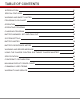
TABLE OF CONTENTS INTRODUCTION 01 SPECIAL FEATURES 03 WARNING AND SAFETY NOTES 05 PROGRAM FLOW CHART 08 OPERATION 09 OPERATING PROGRAM 10 CHARGING PROGRAM 14 BATTERY MEMORY SET AND CALL OUT 15 SYSTEM SETTING 17 BATTERY METER 19 BATTERY RESISTANCE METER 20 WARNING AND ERROR MESSAGE 21 USING THE CHARGE CONTROL SOFTWARE “CHARGE MASTER” 22 SPECIFICATION 24 CONFORMITY DECLARATION 25 MAXIMUM CIRCUIT POWER CHART 26 COMMONLY USED TERMS 28 WARRANTY AND SERVICE 29
INTRODUCTION Congratulations on your choice of SKYRC Ultimate 1000W Balance Charger/Discharger. This unit is simple to use, but the operation of a sophisticated charger such as SKYRC Ultimate 1000W does require some knowledge on the part of the user. These operating instructions are designed to ensure that you quickly become familiar with its functions.
INTRODUCTION Please read this entire operating manual completely and attentively before using this product, as it covers a wide range of information on operating and safety. Or please do use this product in company with a specialist! Output Display Large 2x16 LCD for Easy Reading Balancing Port Temperature Sensor Port Batt Prog DEC/INC /Stop Button Button Start/Enter Button Cooling Fan USB Port for 1. PC Control & Firmware Upgrade 2.
SPECIAL FEATURES Optimized Operating Software Ultimate 1000W features the so-called AUTO function that set the feeding current during the process of charging or discharging. Especially for lithium batteries, it can prevent the overcharging which may lead to an explosion due to the user's fault. It can disconnect the circuit automatically and alarm once detecting any malfunction.
SPECIAL FEATURES Fast and Storage Mode of Lithium Battery Purposes to charge lithium battery varies, 'fast' charge reduce the duration of charging, whereas 'store' state can control the final voltage of your battery, so as to store for a long time and protect useful time of the battery. Re-Peak Mode of NiMH/NiCd Battery In re-peak charge mode, the charger can peak charge the battery once, twice or three times in a row automatically. This is good for making certain the battery is fully charged.
WARNING AND SAFETY NOTES These warnings and safety notes are particularly important. Please follow the instructions for maximum safety; otherwise the charger and the battery can be damaged or at worst it can cause a fire. Never leave the charger unattended when it is connected to its power supply. If any malfunction is found, TERMINATE THE PROCESS AT ONCE and refer to the operation manual. Keep the charger well away from dust, damp, rain, heat, direct sunshine and vibration. Never drop it.
WARNING AND SAFETY NOTES Never attempt to charge or discharge the following types of batteries. A battery pack which consists of different types of cells (including different manufacturers) A battery that is already fully charged or just slightly discharged. Non-rechargeable batteries (Explosion hazard). Batteries that require a different charge technique from NiCd, NiMh, LiPo or Gel cell (Pb, Lead acid). A faulty or damaged battery. A battery fitted with an integral charge circuit or a protection circuit.
WARNING AND SAFETY NOTES Attention should be paid to the connection of lithium battery especially. Do not attempt to disassemble the battery pack arbitrarily. Please get highlighted that lithium battery packs can be wired in parallel and in series. In the parallel connection, the battery s capacity is calculated by multiplying single battery capacity by the number of cells with total voltage stay the same. The voltages imbalance may cause fire or explosion .
PROGRAM FLOW CHART INC DEC PROGRAM SELECT LiPo BATT INC LiFe BALANCE 2.0A 6.6V (2S) DEC LiHV BALANCE 2.0A 7.6V (2S) DEC 4.20 4.19 4.19 V 0.00 0.00 0.00 V DEC 1: 5mΩ 2: 3mΩ 3: 4mΩ 4: 3mΩ DEC Rest Time CHG>DCHG 10Min DEC DEC Lilo CHARGE 2.0A 7.2V (2S) DEC LiFe CHARGE 2.0A 6.6V (2S) DEC LiHV CHARGE 2.0A 7.6V (2S) DEC INC LiPo FAST CHG 2.0A 7.4V (2S) DEC Lilo FAST CHG 2.0A 7.2V (2S) DEC LiFe FAST CHG 2.0A 6.6V (2S) DEC LiHV FAST CHG 2.0A 7.6V (2S) DEC INC LiPo STORAGE 2.0A 7.
OPERATION BATT PROG / STOP Button: It is used to stop the progress or go back to previous step/screen DEC Button: It is used to go through the menus and decrease the parameter value INC Button: It is used to go through the menus and increase the parameter value ENTER / START Button: It is used to enter parameter or store parameter on screen. When you are willing to alter the parameter value in the program, press the START/ENTER button to make it blink then change the value by pressing DEC and INC button.
OPERATING PROGRAM Here is the detailed procedure to make the charger work. All the screens and operations will take Li-Po BALANCE CHARGE program for example, 1. Connection 1). Connecting to power source There are 2 kinds of power source: DC power supply and Lead Acid battery. After you connect the power source to the charger, when you power up the charger for the first time or load the factory default setting, please follow below steps, Power Supply? >DC Power Supply ENTER DC Supply: Cut Volt.: 30.0A 11.
OPERATING PROGRAM Important Notice To take advantage of Ultimate 1000W’s full power capability, the power source should be 30V DC, and output power should be capable of 1200W or higher. Low quality DC power source may damage your Ultimate 1000W charger. We recommend you to choose EFUEL 1200W Power Supply. Connecting to Battery supply If you use the battery as the power source, please do set the right battery current and cut voltage, or it will get damage to the charger and the charging battery. 2).
OPERATING PROGRAM 2. Getting started Locate the flowcharts show the entire programming menu. It is highly recommended to have these flowcharts handy while learning to operate this charger. There are two main ways in which to set the charger. (1) A memory profile is available for setting and storing pertinent information for up to 10 different batteries. Once a battery's information is stored into a memory it will be retained until changed again manually.
OPERATING PROGRAM R:3SER S:3SER CONFIRM(ENTER) START/ENTER LP4s 1.5A 12.14V BAL 000:50 00022 R shows the number of cells detected by the charger and S is the number of cells set by you at the previous screen. If both numbers are identical, press START/ENTER to start charging process. 7. Charging Status Monitor During charge process, real-time status will be showed as left screen.
OPERATING PROGRAM 8. Program Stop During the charging process, press STOP to stop the charging process. 9. Program Complete When the charging process finishes, an audible sound will be heard. Charging Program Depends on different battery type, the operation programs are different.
BATTERY MEMORY SET AND CALL OUT REGENERATIVE DISCHARGE Regenerative Discharge transforms most of the energy from the discharging battery pack to the Lead Acid battery powering the charger. The regenerative discharge current can reach to 40A Max. It works only when the power source is 6P or 12P Lead Acid battery. For factory default setting, the Regenerative Discharge function is disabled.
BATTERY MEMORY SET AND CALL OUT CHARGE CURRENT 4.9A Set the charge current(0.1-40.0A). DEC INC DSCH CURRENT 2.0A Set the discharge current (0.1A-8.0A). DEC INC DSCH VOLTAGE 3.0V/CELL Set the discharge voltage(3.0-3.3V/Cell). DEC INC TVC=YOUR RISK! 4.20V Set the terminal voltage(4.18-4.25V). DEC INC SAVE PROGRAM ENTER Press ENTER to save program. START/ENTER SAVE PROGRAM SAVE…. [ BATT MEMORY 1 ] LiPo 7.4V (2S) Indicate the battery type and battery cell of the saved profile.
SYSTEM SETTING It is essential for users to do system settings before use. After entering system setting program, the screen displays the following information in sequence and the user can change the value of parameter on each screen. When you are willing to alter the parameter value in the program, press START/ENTER to make it blink then change the value with INC or DEC. The value will be stored by pressing START/ENTER once.
SYSTEM SETTING SELECTION ITEM USE Regenerative Discharger? > Y Ext. Temp Int. Temp · 18 0C 37C N/Y DESCRIPTION Activate/Disable the Regenerative Discharge function The external temperature of the battery. The internal temperature of the charger. Load Factory Set Enter Press ENTER to load factory default setting. Version HW:1.00 FW: 1.10 It indicates the hardware and firmware version.
BATTERY METER The user can check battery's total voltage, the highest voltage, the lowest voltage and each cell's voltage. Please connect the battery to the charger main battery lead to battery socket and balance wires to balance board. This diagram shows the correct way to connect your battery to check the voltage. BATT/PROGRAM BATT METER Battery Pack Press the START/ENTER to enter the Lithium Battery Meter program. START ENTER 4.20 4.18 4.19 4.18 4.19 V 4.
BATTERY RESISTANCE METER The user can check each cell's resistance. Please connect the battery to the charger main battery lead to battery socket and balance wires to balance socket. 005 003 003 005 004 003 mΩ mΩ This diagram shows the correct way to connect your battery to check the resistance. BATT/PROGRAM BATT RESISTANCE Battery Pack Press the START/ENTER to enter the Lithium Battery Resistance program.
WARNING AND ERROR MESSAGE In case of an error the screen will display the cause of error and emit an audible sound. Incorrect polarity connected. The battery is interrupted. CONNECT ERROR CHECK MAIN PORT The battery connection is wrong. BALANCE CONNECT ERROR The balance connect is wrong. DC IN TOO LOW Input voltage less than 11V. DC IN TOO HIGH Input voltage higher than 30V. CELL ERROR LOW VOLTAGE Voltage of one cell in the battery pack is too low.
USING THE CHARGE CONTROL SOFTWARE “CHARGE MASTER” CHARGE MASTER- FREE PC CONTROL SOFTWARE The free “Charge Master” software gives you unparalleled ability to operate the charger through the computer. You can monitor pack voltage, cell voltage and other data during the charging, view charge date in real-time graphs. And you can initiate, control charging and update firmware from “Charge Master”.
RECOMMENDED PRODUCTS eFUEL 15-30V/50A Power Supply SPECIFICATION Voltage: 100-240V AC Input AC Frequency: 50-60Hz Output Voltage: 15-30V DC±0.5V Output Current: 50A±1A Over Temperature Protection: <65℃ Cooling Method: Cooling Fan Dimensions: 305x170x85mm Net weight: 3.08kg SK-200015 Dual Port Safe Parallel Adapter SPECIFICATION Cell Count: 2~8S Balance Connector Type: XH Fuse Protect Over Current Indicator SK-600071 THE SET CONTAINS 1. SKYRC Ultimate 1000W Charger 2. 2-8S Multiple Balance Board Adapter 3.
SPECIFICATION SPECIFICATION DC Input Voltage : 11-30V Controls: Button Display Type: 2x16 LCD Display Backlight: Blue Case Material: Metal Cooling System: Built-in fan x2pc Case Size: 138x156x76mm Weight: 1240g PC Communications: USB Port for PC Control & Firmware Upgrade External Port: Balance Socket-XH, Temperature Probe Socket, Battery Socket, DC Input, Micro USB Port for PC and Wi-Fi Module for Smart Phone Control Delta Peak Detection: NiMH/NiCad: 3-15mV/cell (Default 4mV/cell) Charge Cutoff Temperature
CONFORMITY DECLARATION SKYRC Ultimate 1000W satisfy all relevant and mandatory CE directives and FCC Part 15 Subpart B: 2012.
MAXIMUM CIRCUIT POWER CHART Maximum circuit power chart The actual amount of charge current feeding to the battery is automatically be limited to 1000 Watts, so not to exceed the charger's maximum rated charging power. The maximum discharge power is approximately 80 Watts. The discharge current delivered to the charger is limited by charger's internal thermal sensor for maximum discharge current.
MAXIMUM CIRCUIT POWER CHART Battery Type NiCd/NiMH Pb Ultimate 1000W 1000W 80W 2 2.4 3.0 40.0 8.0 3 3.6 4.5 40.0 8.0 4 4.8 6.0 40.0 8.0 5 6.0 7.5 40.0 8.0 6 7.2 9.0 40.0 8.0 7 8.4 10.5 40.0 7.6 8 9.6 12.0 40.0 6.6 9 10.8 13.5 40.0 5.9 10 12.0 15.0 40.0 5.3 11 13.2 16.5 40.0 4.8 12 14.4 18.0 40.0 4.4 13 15.6 19.5 40.0 4.1 14 16.8 21.0 40.0 3.8 15 18.0 22.5 40.0 3.5 16 19.2 24.0 40.0 3.3 17 20.4 25.5 39.2 3.1 18 21.6 27.
COMMONLY USED TERMS Commonly used terms Final charge voltage: the voltage at which the battery's charge limit (capacity limit) is reached. The charge process switches from a high current to a low maintenance rate (trickle charge) at this point. From this point on further high current charging would cause overheating and eventual terminal damage to the pack. Final discharge voltage: the voltage at which the battery's discharge limit is reached.
WARRANTY AND SERVICE Liability exclusion This charger is designed and approved exclusively for use with the types of battery stated in this Instruction Manual. SkyRC accepts no liability of any kind if the charger is used for any purpose other than that stated. We are unable to ensure that you follow the instructions supplied with the charger, and we have no control over the methods you employ for using, operating and maintaining the device.
Manufactured by SKYRC TECHNOLOGY CO., LTD. www.skyrc.com All specifications and figures are subject to change without notice. Printed in China 2014.