
Operation Manual

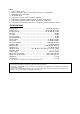


DESCRIPTION
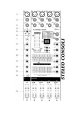
FIG. 1
1. XLR mic input suitable for balanced and unbalanced signals.
2. 6.3 mm Line input suitable for balanced and unbalanced signals.
3. 6.3 mm Line insert Jack, + TIP input, - RING output.
4. Overload detection LED of the input signal on each channel.
5. Gain control on each channel with 40 dB control range.
6. Switchable high-pass filter removing the frequencies below 100 Hz.
7. High frequency level control providing ± 15 dB cut or boost on a frequency of 10 kHz.
8. Mid frequency tune control, tuning the frequencies from 350 Hz - 8 kHz.
9. Mid frequency level control providing ± 15 dB cut or boost on a frequency of 350 Hz - 8 kHz.
10. Low frequency level control providing ± 15 dB cut or boost on a frequency of 100 Hz.
11. AUX 1 level control for each channel. Sets the level of the AUX1 bus for every Line.
12. AUX 2 level control for each channel. Sets the level of the AUX1 bus and the effect level for every
Line.
13. Volume control for every Line. Sets the volume between left and right of the master output
channel.
14. Pause button: Press this button to pause, press again to resume play
15. Volume level control: Sets the signal strength for the left and right channel.
16. Left Line balanced XLR output, +4 dB.
17. Left Line unbalanced 6.3 mm output Jack, +4 dB.
18. Left Line unbalanced 6.3 mm output Jack, -10 dB.
19. Right Line balanced XLR output, +4 dB.
20. Right Line unbalanced 6.3 mm output Jack, +4 dB.
21. Right Line unbalanced 6.3 mm output Jack, -10 dB.
22. AUX 1 Line balanced XLR output, +4 dB.
23. AUX 1 Line unbalanced 6.3 mm output Jack, +4 dB.
24. AUX 1 Line unbalanced 6.3 mm output Jack, -10 dB.
25. AUX 2 Line balanced XLR output, +4 dB.
26. AUX 2 Line unbalanced 6.3 mm output Jack, +4 dB.
27. AUX 2 Line unbalanced 6.3 mm output Jack, -10 dB.
28. VU meter: displays the output level of the left and right main bus.
29. VU meter switch: Switches between the left channel power amplifier and the left main bus output
signal.
30. VU meter switch: Switches between the right channel power amplifier and the right main bus
output signal.
31. Effect time, digital indicator, 1-16 bands
32. Effect time, digital indicator, increases an effect
33. Effect time, digital indicator, decreases an effect
34. Effect feedback 6.3 mm input Jack.
35. Stereo headphones 6.3 mm output Jack.
36. Stereo headphones level control.
37. Effect level control for the high frequencies, ± 12 dB cut or boost on a frequency of 3.5 kHz.
38. Effect level control for the low frequencies, ± 12 dB cut or boost on a frequency of 100 Hz.
39. Effect control: Sets the delay of the effects.
40. Effect volume control: Sets the volume between left and right of the master output channel.
41. Effect volume level control: Sets the signal strength of the master output for the left and right
channel.
42. Dual 7-band graphic equalizer: Individual control of the right and left channel.
63 Hz 160 Hz 400 Hz 1 kHz 2.5 kHz 6,3 kHz 16 kHz (@ ± 12 dB)
43. Left channel level control: Sets the left AMP input level and the master output level.
44. Right channel level control: Sets the right AMP input level and the master output level.
45. AUX 1 level control: Sets the signal level strength of AUX 1 channel.
46. AUX 2 level control: Sets the signal level strength of AUX 2 channel.
47. +48V Phantom power LED indicator