
Installation and Operation Instructions


Skytech: CON1001-1
REV. 2-22-22 Page 3
LEARNING TRANSMITTER TO RECEIVER
Each transmitter uses a unique security code. It will be necessary to press the LEARN button on the receiver to accept the transmitter
security code upon initial use, if batteries are replaced, or if a replacement transmitter is purchased from your dealer or the factory. In
order for the receiver to accept the transmitter security code, be sure the slide button on the receiver is in the REMOTE position; the
receiver will not LEARN if the slide switch is in the ON or OFF position. The LEARN button in located on the front face of the receiver;
inside the small hole labeled LEARN. Using a small screwdriver or end of a paperclip gently press and release the black LEARN button
inside the hole. When you release the LEARN button the receiver will emit an audible “beep”. After the receiver emits the beep press
ANY transmitter button and release. The receiver will emit several beeps indicating that the transmitter’s code has been accepted into
the receiver.
The microprocessor that controls the security code matching procedure is controlled by a timing function. If you are unsuccessful in
matching the security code on the rst attempt, wait 1 - 2 minutes before trying again--this delay allows the microprocessor to reset its
timer circuitry--and try up to two or three more times.
IMPORTANT NOTE: Operation of these controls is dependent on which wire is attached to which terminal. If operation
of control does not correspond to operating buttons on transmitter, reverse wire installation at the receiver or at control.
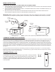
Remote Receiver
Receiver
Slide
Button
REMOTE
OFF
PULSE MODE
Terminals
RED Wire
1/4” Female
Terminal
BLACK Wire
1/4” Female
Terminal
(Back of Receiver)
BLACK Wire
1/4” Female
Terminal
RED Wire
1/4” Female
Terminal
LEARN
ON
NOTE: Up to 6.3 VDC of power is provided at the receiver terminal.
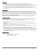
TRANSMITTER WALL CLIP
The transmitter can be hung on a wall using the clip provided. If the clip is installed
on a solid wood wall, drill 1/8” pilot holes and install with the screws provided. If it is
installed on a plaster/wallboard wall, rst drill two 1/4” holes into the wall. Then use
a hammer to tap in the two plastic wall anchors ush with the wall; then install the
screws provided.
WALL CLIP
SLOT
WALL CLIP
BATTERY
COMPARTMENT
WIRING INSTRUCTIONS
CONNECTING THE RECEIVER TO A VALVE WITH THE LATCHING SOLENOID
1. Connect the BLACK 18 gage stranded wire with the 1/4’ female terminal from the receiver to the BLACK wire with the
1/4” male terminals from the valve solenoid.
2. Connect the RED 18 gage stranded wire with the 1/4’ female terminal from the receiver to the RED wire with the 1/4”
male terminals from the valve solenoid.
3. After receiver wires are connected to the valve solenoid wire make sure the receiver shield is located over the
receiver and then locate the receiver in an area that will not exceed the 130°F.