
User's Manual

SKYTECH 1001SR/P TH
REV. 09/02
Page 1 of 6
1001SR/P TH
INSTALLATION AND OPERATING INSTRUCTIONS
MULIT-FUNCTION WIRELESS REMOTE CONTROL SYSTEM
FOR OPERATING SERVO MOTORS VALVES OR PULSE SOLENOIDS VALVES
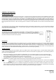
INTRODUCTION
This remote control system was developed to provide a safe, reliable, and user-friendly remote control system for gas heating appliances. The
system is operated manually from the transmitter. The system operates on radio frequencies (RF) within a 20' range using non-directional
signals. The system operates on one of 255 security codes that are programmed into the transmitter at the factory; the remote receiver's code
must be matched to that of the transmitter prior to initial use.
Review THERMO SAFETY SECTION under RECEIVER section. This high temperature safety feature shuts down
the appliance when a potentially unsafe condition exists.
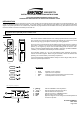
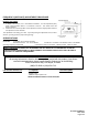
TRANSMITTER
This remote control SYSTEM offers the user a battery-operated remote control to power
up to a 6 VDC servo motor or solenoid such as those used with gas valves used in some
heater rated gas logs, gas fireplaces and other gas heating appliances.
The servo motor or solenoid circuit uses the battery power from the receiver to operate a
servo motor or solenoid. The circuit has reversing polarity software which reverses the
positive (+) and negative (-) output of the receiver's battery power to drive the servo
motor or solenoid forward/backward (HI/LO FLAME) or open/close (FLAME SOLENOID
- ON/OFF). The SYSTEM is controlled by the remote transmitter.
The transmitter operates on a (2) 1.5V AAA batteries made specifically for remote
controls and electronic lighters. Before using the transmitter, remove the insulation tab
protecting one end of the battery in the battery compartment.
It is recommended that ALKALINE batteries always be used for longer battery life and
maximum operational performance.
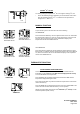
KEY SETINGS
• ON/HI -Operates unit to on position.
• LO/OFF - Operates unit to off position
• MODE - Changes unit from manual feature to thermo feature.
• SET - Sets temperature in thermo in feature.
1. DISPLAY Indicates CURRENT room temperature .
2.
0
F OR
0
C Indicates degrees Fahrenheit or Celsius.
3. FLAME Indicates burner/valve in operation.
4. ROOM Indicates remote is in THERMO operation.
5. TEMP Appears during manual operation.
6. SET Appears d uring time the of setting the desired temperature in
the thermo operation.
ON/HI
MODE
LO/OFF
BUTTON
WALL CLIP
SLOT
12V
BATTERY
COMPARTMENT
FRONT BACK
LO/OFF
SET
ON/HI
BUTTON
MODE
BUTTON
SET
BUTTON
ROOM
LCD - Liquid Crystal Display
TEMP
1
2
3
SET4
5
6
ON/HI
MODE
LO/OFF
SET
1
2
3
4