
Installation and Operating Instructions


DRAFT
This is a DRAFT copy and is subject to change. It is not approved for release. DO NOT COPY!
2
Hearth & Home Technologies • RCT-MLT-IV Remote Control Instructions • 100-908 Rev. D • 12/19
Figure 1
INSTALLATION INSTRUCTIONS
Installing Electrical Service to the Junction Box
RECEIVER WIRING INSTRUCTIONS
Incorrect wiring connections WILL cause damage to the gas
valve or electronic module operating the gas appliance and
may also damage the remote receiver.
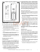
Wiring Flame Function (Standing Pilot, DSI, IPI)
Connect the remote receiver by connecting the two red wires
leading from the remote receiver to the red and brown remote
wires labeled “FOR USE WITH REMOTE OR WALL SWITCH
ONLY”. See Figure 2.
Figure 2.
Alternative Wiring for units with a wall switch
Disconnect the wall switch wire from the TH terminal on
the valve and connect this wire to male connector supplied
on the receiver. Connect remaining female connector from
receiver to the TH terminal on the valve.
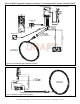
Adding Optional Fan/Blower
Plug 2-prong fan cord directly into the 3 prong polarized plug
on the back of the receiver (see Figure 3). This receptacle
output is 110/120 VAC, 3 AMP.
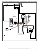
Wire Colors
• Gas Valve - Millivolt or
Electronic Ignition .............................................. Red
• Fan/Blower - 110 VAC .........................Plug from Fan
• Flame Controller - HI/LO solenoid ..................Orange
Figure 3. Adding Fan/Blower
WARNING: LEAVE ELECTRICAL POWER OFF
AT THIS TIME. DO NOT RESTORE POWER UN-
TIL THE REMOTE CONTROL SYSTEM IS COM-
PLETELY INSTALLED.
2. Feed the electrical service wires through the Romex
clamp and secure the wires to the clamp.
3. Using the wire nuts provided, connect the service wires
to the junction box. The black wires to the black service
wire, the white wires to the white service wire, and the
service ground wire to the ground stud of the junction
box.
4. Re-attach the cover plate to the outside of the replace.
NOTE: Some appliances do not have a cover plate. In-
stead, there is a hole through which the Romex clamp is
attached to the outer wrap.
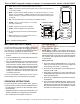
1. Remove the electrical cover plate from the lower side
of the replace. Remove the knock-out from the plate
and attach the Romex clamp (screws to the outside)
(see Figure 1).
WARNING: TURN ELECTRICAL POWER OFF AT
THE CIRCUIT BREAKER BEFORE BEGINNING
THIS INSTALLATION.
ACCESS HOLE
COVER
PLATE
110 VAC
SERVICE
NOTE: If junction box contains 2-prong receptacles, a standard
3 to 2 prong adapter will be required to be obtained from an
independent source.
REMOTE RECEIVER
Important: The remote receiver should be positioned
close to front in right or left corner where ambient
temperatures do not exceed 170º F.
The remote receiver is powered by 110-120VAC. It plugs
into a standard polarized duplex receptacle.
Locating Receiver and Operating Functions
This remote receiver can be positioned under the rebox
in the control compartment of the replace if ambient tem-
peratures do not exceed 170º F. This system is designed
to control the following components:
ON/OFF
SWITCH REMOTE SWITCH
PIGTAIL
RED
RED
BROWN
RED
TH
TH
WALL
SWITCH
TP
TP
VALVE
RED
ORANGE
RED
ORANGE
(Receptacle on back)
Line cord
from fan