
Installation and Operating Instructions


DRAFT
This is a DRAFT copy and is subject to change. It is not approved for release. DO NOT COPY!
9
Hearth & Home Technologies • RCT-MLT-IV Remote Control Instructions • 100-908 Rev. D • 12/19
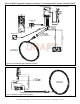
Figure 9. Intermittent Pilot Ignition (IPI) Wiring Diagram
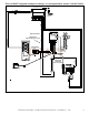
Figure 10. Standing Pilot Ignition Wiring Diagram
TRANSFORMER
3 VAC
PLUG IN
R
E
D
BATTERY PACK
THERMOSTAT
WIRE ASSEMBLY
JUMPER WIRE
(TO BROWN)
(WHEN APPLICABLE)
ORANGE
GREEN
VALVE
GROUND TO
FIREPLACE
CHASSIS
WHITE
ORANGE
IGNITION MODULE 3 VAC INTERMITTENT PILOT IGNITOR
HOT
NEUTRAL
I
S
THERMOSTAT
WIRE ASSEMBLY
PIEZO
WHITE
RED
VALVE
PILOT
THERMOCOUPLE