
Installation Guide


REV. 3/19/05 Page 1 of 14
3301PF
INSTALLATION AND OPERATING INSTRUCTIONS
INTRODUCTION
This SKYTECH remote control system was developed to provide a safe, reliable, and user-friendly remote control system for gas heating
appliance. The system can be operated thermostatically or manually from the transmitter. The system operates on radio frequencies (RF)
within a 20'’range using non-directional signals. The system operates one of 1,048,576 security codes that are programmed into the transmitter
at the factory.
IMPORTANT:
IMPORTANT:
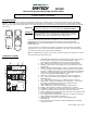
The transmitter operates on 2AAA-size 1.5V batteries. It is recommended that ALKALINE
batteries always be used for longer battery life and maximum operational performance.
IMPORTANT: New or fully charged batteries are essential for proper operation of the multi-
function transmitter.
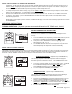
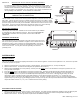
Insert 2 AAA-size 1.5 V batteries into the battery compartment on the back of the transmitter,
positioning the (+) and (-) ends of the batteries as indicated on the casing. When the batteries
are inserted, the screen (with similar numbers) will display.
Note: If a LOW battery icon appears on the screen, check the position of the batteries; a reversed
battery will activate the LOW battery icon.
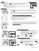
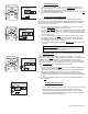
LCD DISPLAY SCREEN
1. PROGRAM FOR: Flashes when programming days of week and periods of
the day. When in normal state, only current DAY displays. When
programming or in PROGRAM mode, both day and week will appear.
2. DAY –Flashes when current day or day of week is being programmed.
3. PERIOD – Flashes when current period of day or period of week is being
programmed.
4. MODE – Indicates operation MODE of system - ON indicates the system is
on, either manually or thermostatically – OFF indicates the entire system is
turned off - THERMO indicates the system will automatically cycle ON/OFF,
depending on programmed SET temperature - PROGRAM – indicates the
system is operating with PROGRAMMED settings.
5. START AT – Flashes when programming the time to turn system ON.
6. SET – Indicates desired SET room temperature, when in THERMO or
PROGRAM mode.
7. F
0
/ C
0
– Factory programmed in F
0
. (C
0
indicates degrees in Celsius)
8. TIME/TEMP – Displays the CURRENT room temperature. In same frame,
the current time will display in AM or PM. You must depress the
TIME/TIMER button to display current time.
9. LOW – Battery power is low. Replace batteries within 2 weeks.
10. TIMER – When displayed, indicates countdown timer in operation.
11. OVERRIDE – Displays when “programmed” SET temperature is overridden.
12. FLAME – Single flame symbol indicates burner/valve is operational.
13. HOLD – Displays when “programmed” SET temperature is overridden and will
hold that temperature until cancelled.
14. CP – Displays when CHILD PROOF “LOCK OUT” is engaged. Pressing the
UP and TIMER buttons together, engages CP.
15. SWING- Displays in SET frame when setting TEMPERATURE
DIFFERNTIAL.
16. FAN – Indicates the fan is ON (when fan blade displayed), the word OFF
indicates fan is OFF.
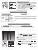
Before operating remote control, transmitter and receiver must have
matching security codes. See section: MATCHING SECURITY CODES
Review THERMO SAFETY SECTION under TRANSMITTER section and
RECEIVER section. These signal/temperature safety features shut down
the fireplace system when a potentially unsafe condition exists.
TIME
AM
START
AT
PROGRAM
FOR
SU MO TU WE TH FR SA
MORN DAY EVE NITE
PM
THERMO
ON
LOW
OFF
PROGRAM
OVERRIDE HOLD
TEMP
FLAME
TIMER
SWING
1
2
3
11
13
7
6
14
8
SET
15
12
10
4
9
5
FAN
OFF
OFF
16
IF YOU CANNOT READ OR UNDERSTAND THESE INSTALLATION INSTRUCTIONS DO NOT
ATTEMPT TO INSTALL OR OPERATE
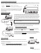
Cover Closed
UP
DOWN
MODE
TIMER
TIME
SET
Cover
Open
PROG
AHEAD
BACK
FAN
UP
DOWN
MODE