® OWNERS/OPERATORS MANUAL Model 6042 (S/N 0160004111 thru 0160037382) OA1531 Keep this manual with the vehicle at all times. 3126022 B Printed in U.S.A.
WARNING: Improper operation of this vehicle can cause injury or death. Only trained and authorized operators should operate this vehicle. Before starting the engine, do the following: 1. Read this owner/operators manual. 2. Read all the safety decals on the vehicle. 3. Clear the area of other persons. Learn and practice safe use of vehicle controls in a safe, clear area before you operate this vehicle on a worksite.
Table of Contents Introduction General Maintenance The Manual....................................2 Replacement Parts ........................2 Reports ..........................................2 Safety Practices Disclaimer......................................3 Hazard Classification System........3 Accident Prevention Tags..............5 New or Additional Operators .........5 Instructional Symbols ....................6 Hazard Symbols ............................7 Avoidance Symbols .......................
Introduction Introduction The Manual This Owners/Operators Manual provides the information you need to properly operate and maintain this vehicle. IMPORTANT! Before you operate this vehicle, read this manual completely and carefully so you will understand the safety instructions and the operation of the controls and safety equipment. You must comply with all Danger, Warning, and Caution notices. They are for your benefit.
Safety Practices Safety Practices Disclaimer JLG reserves the right to make changes on and to add improvements upon its products at any time without public notice or obligation. JLG also reserves the right to discontinue manufacturing any product at its discretion at any time. NOTICE: Under OSHA rules, it is the responsibility of the employer to provide operator training. Successful completion and certification of Safety Training for Rough Terrain Forklifts is required.
Safety Practices Signal Word A signal word is a distinctive word located on hazard decals and used throughout this manual that alerts the viewer to the existence of and relative degree of the hazard. DANGER: The signal word “DANGER” indicates an imminently hazardous situation which, if not avoided, will result in death or serious personal injury. WARNING: The signal word “WARNING” indicates a potentially hazardous situation which, if not avoided, could result in death or serious personal injury.
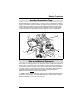
Safety Practices Accident Prevention Tags Before beginning any maintenance or service, place an Accident Prevention Tag (1) on both the starter key switch (2) and the steering wheel (3), stating that the vehicle should not be operated. Actual Accident Prevention Tags, which can be punched out and used, are included as the last page of this manual. Retain these Accident Prevention Tags for reuse at a later date.
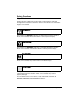
Safety Practices Instructional Symbols The following symbol definitions will help you understand all hazard related decals and load charts used on this vehicle. OP0330 Safety Alert Symbol OH2100 Read Operator’s Manual OH2090 Fasten Seat Belt OH3100 This Symbol Signifies That Specific Attachments Must Only Be Used On Vehicles Equipped With Auxiliary Hydraulics. Always Connect Couplers.
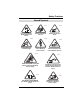
Safety Practices Hazard Symbols OH2120 OH2110 OH2130 - Lead Acid Batteries Generate Explosive Gases Rotating Fan Blades Can Cut OH2150 OH2300 Rotating Belts Can Cut Or Entangle Vehicle Tipover Can Crush OH2140 Electrocution Can Cause Death Or Serious Injury Vehicle Roll Away Can Cause Death Or Serious OH3160 OH3110 AVOID CRUSHING, Falling Off Vehicle Can Cause Death Or Serious Injury Swinging Loads Can Cause Vehicle Tipover Which Can Result In Death Or Serious Injury OH2161 OU1450 FALLING O
Safety Practices Avoidance Symbols OH2320 OH2330 Keep Flames and Ignition Sources Away Keep Lit Cigarettes Away OH2310 Keep Away From Rotating Fan Blades Stop Operation At This Point OH2280 Do Not Raise Boom While On A Slope OH2270 OU1520 Do Not Travel With Boom Raised OU1510 Prohibition Symbol.
Safety Practices Avoidance Symbols (cont’d) OH2260 Engage Parking Brake OH2250 Keep Clear Of Power Lines OH2240 Do Not Travel With Personnel In Work Platform OH2230 Carry No Riders OH2170 OU1460 Use Only Compliant Work Platforms To Raise Or Lower Personnel DO NOT Use Ether Or Other High Energy Starting Aids. Engine Equipped With Grid Heating System.
Safety Practices Personal Considerations 1. Seat Belt Always fasten the seat belt before starting the engine. 2. Clothing and Safety Gear DO NOT wear loose clothing or jewelry that can get caught on controls or moving parts. Wear protective clothing and personal safety gear issued or called for by job conditions. 3.
Safety Practices C. Ether or High Energy Starting Aids (Optional) The engine utilizes a grid heating system inside the induction manifold for cold starting conditions. WARNING: This diesel engine uses a grid heating system inside the induction manifold. DO NOT use ether or any high energy fuels to assist starting. An explosion may cause death or serious personal injury or engine damage. DO NOT use ether or any other high energy starting aids during cold starting.
Safety Practices E. Battery The following WARNING is intended to supplement and does not replace the warnings and information provided on the battery by the battery manufacturer. When jump starting the vehicle, carefully follow instructions found under “Jump Starting” on page 58. - OS0621 Keep sparks, flames and lit smoking materials away from the battery at all times. Lead acid batteries generate explosive gases. Severe chemical burns can result from improper handling of battery electrolyte.
Safety Practices 5. Moving Parts Hazard DO NOT place limbs near moving parts. Severing of any body part can result. Turn OFF engine and wait until fan and belts stop moving before servicing. MOVING PARTS can cut. Keep clear of fan and belts while engine is running. MOVING PARTS can entangle. OT0810 6. Lowering Boom or Falling Load Hazard DO NOT get under a raised boom unless it is blocked up safely.
Safety Practices Operational Considerations 1. Preparation and Prevention Know the location and function of all vehicle controls. Make sure all persons are away from the vehicle and that the travel select lever is in the (N) NEUTRAL position and the Neutral Lock Lever is in the (N) NEUTRAL LOCK position with the parking brake switch engaged before starting the engine. Holes, obstructions, debris and other worksite hazards can cause death or serious personal injury.
Safety Practices 4. Underground Hazards Know the location of all underground hazards before operating this vehicle in a new area or worksite. Electrical cables, gas and water pipes, sewer, or other underground objects can cause death or serious personal injury. Contact your local underground utility service or diggers hotline to mark all underground hazards. 5.
Safety Practices 6. Elevating Personnel Use only a compliant work platform meeting the ASME B56.6 standards for lifting and lowering personnel. NEVER transport personnel in a work platform for even the shortest distance. Death or serious personal injury can occur if these rules are not obeyed. Riders can fall and be crushed or run over. Avoid accidents. For other specific precautions, see “Elevating Personnel” on page 84.
Safety Practices 7. Tip Over Hazard VEHICLE TIPOVER can result in death or serious injury. DANGER MAINTAIN proper tire pressure at all times. DO NOT raise boom while on a slope unless load is level. DO NOT travel with the boom raised. OS0086 Traveling with the boom raised is dangerous and can cause tipover. Keep the boom as low as possible. Travel with extreme caution and at the slowest possible speed. Keep the vehicle under control at all times.
Safety Practices 9. Tire Pressure VEHICLE TIPOVER can result in death or serious injury. DANGER DO NOT travel with the boom raised. DO NOT raise boom while on a slope unless load is level. MAINTAIN proper tire pressure at all times. OS0085 MAINTAIN proper tire pressures at all times. An underpressurized tire(s) adversely affects vehicle stability. If proper tire pressures are not maintained, this vehicle can tip over.
Safety Practices 11. Slopes DO NOT park the vehicle on an incline and leave it unattended. • Driving across a slope is dangerous, as unexpected changes in the slope can cause tipover. Ascend or descend slopes slowly and with caution. • Ascend or descend slopes with the heavy end of the vehicle pointing up the slope. NOTE: The rear of the vehicle is normally considered the heavy end unless the carriage is fully loaded. In this case the front of the vehicle is now the heavy end.
Safety Practices Equipment Considerations WARNING: DO NOT modify or alter (weld, drill, etc.) any part of this vehicle without first consulting JLG. Modifications can weaken the structure creating a hazard that can cause death or serious personal injury. DO NOT by-pass or disconnect any electrical or hydraulic circuits. Consult the JLG Service Department or your local Sky Trak Distributor if any circuit is malfunctioning.
Safety Practices 5 3 7 6 2 1. Read operator's manual before operating. 3. Allow no riders. 2. Fasten seat belt. 4. Use a compliant work platform to lift or lower personnel. DANGER AVOID CRUSHING if vehicle tips. Jumping can result in death or serious injury. DO NOT JUMP. Brace yourself. Stay in cab. Keep seat belt on.
Safety Practices 7 2 6 5 3 4 1 OA1670 Item 1 22 Part Number Quantity 2 3 4 5 6 4110184 4110172 4110389 4107442 4105262 4109791 2 1 1 1 1 1 7 4110460 2 Decal Description Moving Parts Warning Explosive Gases Warning Elevating Personnel Warning Boom Extend Letters Boom Angle Indicator Emergency Exit (Enclosed Cab Only) Ether Starting Warning (Optional Grid Heater Cold Start Aid) Model 6042 Origin 2/04
Operation Operation Operator Controls Accelerator Pedal Pressing down the accelerator pedal (8) increases engine and hydraulic speed of the vehicle. The pedal is spring-loaded to return to idle speed. Service Brake Pedal Pressing down the brake pedal (9) decreases the speed of the vehicle by applying the service brakes located in the axles. In the event of engine power loss, the service brake pedal can also be used for braking.
Operation Ignition Switch Using the ignition switch key (1), the switch may be turned clockwise from the OFF (2) position to the RUN (3) and START (4) positions. The START position is spring-loaded to return to the RUN position and must be manually held in place for starting. OFF (2) position — The entire electrical system is shut down. RUN (3) position — All controls and indicators are operable.
Operation Steering Select Switch This vehicle has one steering select switch (5) with three positions. The switch is located in the lower switch bank on right side dash panel. Refer to “Steering Modes” on page 67 for detailed information.
Operation Park Brake Switch The Parking Brake Switch (1) has two positions: OS0121 P ENGAGED ............ toggle switch downward P DISENGAGED ........... toggle switch upward OS1323 The Parking Brake Switch (1) must be ENGAGED to permit engine starting. A red LED, on the parking brake switch, and a light in the instrument cluster will indicate the brake is ENGAGED. The parking brake may be used to stop in an EMERGENCY situation.
Operation Neutral Lock Lever The Travel Select Lever (2) is equipped with a neutral lock. The Neutral Lock Lever (3) locks the Travel Select Lever in NEUTRAL or unlocks the Travel Select Lever so that it can be moved into the FORWARD or REVERSE drive position. 3 2 ND 4 5 OH1782 To lock the Travel Select Lever (2) in the NEUTRAL position, place the lever in the NEUTRAL position and move the Neutral Lock Lever (3) to the (N) NEUTRAL LOCK (4) position.
Operation Travel Select Lever The Travel Select Lever (1) has three positions to select direction of travel: F = FORWARD ...............all the way FORWARD N = NEUTRAL ................CENTER position R = REVERSE................ all the way REARWARD OS0340 1 OH1792 To change travel selections, move the lever FORWARD or REARWARD to the desired selection. When the Travel Select Lever is shifted to REVERSE, the back-up alarm will automatically sound.
Operation Gear Select Lever The Gear Select Lever (2) has a twist grip handle with four positions. Vehicles have four forward gears and three reverse gears. OH1803 2 Use first gear for highest torque and pulling power. Use higher gears for higher ground speed. The recommendations listed in the table that follows are guidelines only. Always use good judgement when traveling with a load.
Operation Boom Control Lever The boom control lever (1) is a joystick with variable motion from the center to control the boom functions: Boom Raise.........................move lever backward Boom Lower ........................move lever forward Boom Extend....................... move lever to the right Boom Retract ...................... move lever to the left OH0170 Two boom functions can be accomplished at the same time by moving the lever into the proper quadrant.
Operation Attachment Tilt and Frame Sway Control Lever The attachment tilt and frame sway control (2) is a joystick with four perpendicular motions from the center to control two attachment tilt functions and two frame sway functions: Frame Sway Left ................. move lever to the left Frame Sway Right............... move lever to the right Attachment Tilt Down...........move lever forward OH0410 Attachment Tilt Up ...............
Operation Seat Belt WARNING: Serious bodily injury or death may result from failure to wear the seat belt installed on this vehicle. The seat belt is a critical component of the Operator’s Protective Structure, and is provided for the operator’s protection in case of vehicle upset. The seat belt MUST be worn whenever this vehicle is operated. IMPORTANT! Inspect the seat belt every time it is used, looking for cut or worn webbing, or any defect in the latch assembly.
Operation Operator’s Seat Adjustment The operator’s seat (5) can be adjusted three ways: A. Fore and Aft Adjustment Pull the handle (6) outward to adjust the seat forward and backward. Release the handle to lock the seat in the desired position. B. Suspension Adjustment Turn the knob (7) on the front of the seat to adjust the suspension to correspond with the operator’s weight. Turn clockwise to increase stiffness. Turn counter-clockwise to reduce the stiffness. C.
Operation Instruments and Indicators Hourmeter OS0260 The hourmeter (1) records engine operating hours and has a total readout of 9,999.99 hours. It is located at the lower portion of the instrument cluster on the right side of the dash. Fuel Gauge OH2470 The fuel gauge (2) indicates the quantity of fuel in the fuel tank. The gauge is located in the center of the instrument cluster on the right side of the dash.
Operation Instrument Cluster Light Test Test the bulbs in the instrument cluster before starting the engine. Turn the ignition switch to the RUN position, ALL nine lights in the instrument cluster will come ON for a few seconds and then go out. Replace any bulbs that DO NOT come ON during this test.
Operation Function Indicator Lights A. Stabil-TRAK Indicator Light OH2500 The Stabil-TRAK light (1) will come ON when the system has been activated. The rear axle will lock when one or more of the following conditions exist with the boom above a 40° angle. • Parking Brake Switch engaged • Travel select lever in (N) NEUTRAL • Service brake pedal depressed and held With the boom above a 40° angle and traveling in a forward or reverse drive gear, the Stabil-TRAK Light will go OFF.
Operation B. Park Brake Light P The park brake light (2) OH2480 illuminates any time the park brake is applied and the ignition switch is in the RUN position. C. High Beam Light (used with optional road light package only) OH2490 The high beam light (3) illuminates when the road option headlights are on full (high) beam and will turn OFF when the headlights are switched to low beam. D.
Operation Warning Indicator Lights There are five additional indicator lights in the instrument cluster that will illuminate during critical circumstances. All five warning indicator lights demand immediate attention and vehicle servicing. In many cases, the vehicle should be shut down AS SOON AS PRACTICAL to prevent serious mechanical failure. The five warning indicator lights are: A.
Operation C. Hydraulic Oil Temperature Warning Indicator Light OH2540 The hydraulic oil temperature light (3) illuminates when the hydraulic oil temperature is too high; above 195° F (91° C). Stop and idle the engine, allowing time for cooling. If the light does not go out after five minutes, shut the vehicle down. 4 P 3 0000 00 OH1810 D.
Operation E. Alternator Charging Warning Indicator Light OH2560 The alternator charging light (1) illuminates when the charging system is not working properly. Service the engine alternator.
Operation Frame Level Indicator The indicator (2) is mounted on the top inside of the Operator's Protective Structure (cab). This is a bubble type indicator which allows the operator to tell if the vehicle has been positioned in a level condition. Always frame sway the vehicle either right or left until the indicator reads zero degrees (0°). If zero cannot be achieved, then reposition the vehicle until it is level before placing the load. NOTE: Maximum frame sway is 10° in either direction.
Operation Rear View Mirrors Two rear view mirrors are provided to aid the operator's rear vision. A rectangular flat lens mirror (1) is mounted on the upper left of the cab (2). A convex lens mirror (3) is mounted on the right side of the frame (4). Both mirrors are adjustable to obtain the best rear view by the operator.
Operation Optional Controls Auxiliary Attachment Control Lever The auxiliary attachment control lever (5) controls the functions of an optional attachment that is mounted to the vehicle and requires a hydraulic supply for operation. Some of the optional attachments that require auxiliary hydraulics are: Side Tilt Carriage, Auger,Swing Carriage, and 3 Foot Truss Boom w/Winch.
Operation Worklight Switch (Front, Rear & Boom Worklights) OH2570 This three position rocker switch (1) controls the front, rear and boom worklights. The switch (1) is located in the upper switch bank on the right side dash panel. These lights will only operate when the ignition switch is in the RUN position. • Push the top of the switch in to turn all the worklights OFF. OH2591 • To turn the front and boom worklight ON, position the rocker switch to the center position.
Operation Beacon Light Switch OH2580 This rocker switch (2) turns the beacon light ON and OFF. The switch (2) is located in the upper switch bank on the right side dash panel. This light will only operate when the ignition switch is in the RUN position. • Push the bottom of the switch in to turn the beacon light ON. • Push the top of the switch in to turn the beacon light OFF.
Operation Worklight Switch (with Optional Road Lights) OH2620 This rocker switch (1) activates the worklight system. The switch (1) is located in the upper switch bank on the right side dash panel. This system will only operate when the ignition switch is in the RUN position. See “Parking Lights, Headlights & High/Low Beam Switch” on page 48 for operation of the road lights. • Push the top of the switch IN to DEACTIVATE the entire worklight system.
Operation Emergency Flashers OS1920 The emergency flashers switch (2) is located in the upper switch bank on the right side dash panel. • To ACTIVATE the emergency flashers, push the bottom of the switch IN. • To DEACTIVATE the emergency flashers push the top of the switch IN.
Operation Turn Signals OH2510 The directional signals are ACTIVATED from the lever (1) on the right side of the steering wheel. To activate the left turn signal (2), raise the lever. To activate the right turn signal (3), lower the lever. To deactivate either directional signal, the lever must be manually returned to the center position. The lever will not cancel automatically after a turn. These lights will only operate when the ignition switch is in the RUN position.
Operation Windshield Wiper Control OS1930 This three position rocker switch (8) controls the speed of the windshield wiper. This switch (8) is located in the lower switch bank on the right side dash panel. • To STOP the windshield wiper, push the top of the switch IN. OH2591 • To OPERATE the windshield wiper at LOW speed, position the switch in the CENTER POSITION. OH2601 • To OPERATE the windshield wiper at HIGH speed, push the bottom of the switch IN.
Operation Skylight Wiper Control OH1900 This rocker switch (1) turns the skylight wiper ON and OFF. This switch is located in the lower switch bank on the right side dash panel. • Push the bottom of the switch IN to turn the skylight wiper ON. OH2611 • Push the top of the switch IN to turn the skylight wiper OFF.
Operation Windshield & Skylight Washer Control OS1940 OH1910 This rocker switch (2) is spring loaded to return to the OFF position when released. This switch is located in the lower switch bank on on the right side dash panel. • Pressing down on the bottom of the switch will dispense washer fluid to the windshield and skylight wiper at the same time. The switch must be held in place to activate the washer control. • Release the switch to deactivate the washer control.
Operation Cab Heater & Fan Control OS1950 The cab heater controls (1) are located directly below the switch banks on the right side dash panel. The control panel consists of: a variable speed fan control knob (2) and a temperature control knob (3). Control of air flow to the windshield is made by opening, closing or redirecting the air vent louver on the front dash. The cab is heated by the heater unit positioned under the operators seat.
Operation Rear Window Latch (Figure ) The rear window (5) can be partially opened and secured in place with the rear window latch (6). To open the window, grab the latch handle (7) and pull up and then push the window outward. To close and secure the window, pull the latch handle forward and down. NOTE: In an emergency situation, the operator can exit through the rear window opening by removing the latch pin (8) on the window latch. The window is then free to swing open. 5 1. 8 2. 3.
Operation Pre-Operation Inspection 1. Check safety belt for damage. Check for frayed or cut seat belt webbing, damaged buckles or loose mounting brackets. Make any necessary repairs before operating the vehicle. 2. Check all four tires and rims for damage. Check for proper tire pressure, add air if required. Observe the condition of each tire looking specifically for punctures, cracks, cuts, gouges, bulges or any other damage. Check the condition of each rim for bent flanges or any other damage.
Operation Normal Starting 1. Enter the cab using the hand holds and adjust the seat for comfortable operation. 2. Adjust the mirrors to obtain the best rear view from the operator’s position. WARNING: DO NOT start the engine unless you are in the seat with the seat belt fastened around you. Death or serious personal injury could result if the belt is not securely fastened. 3. Fasten the seat belt. 4. Make sure the parking brake switch is ENGAGED. 5.
Operation Cold Starting The engine is equipped with a 120 volt 750 watt block heater. Block heaters are recommended when temperatures drop below 10° F (-12° C). Temperature ranges will vary when using different oil weights. Consult the engine manufacturer’s manual for other variables. FOR ENGINES EQUIPPED WITH OPTIONAL COLD STARTING AID WARNING: This diesel engine uses a grid heating system inside the induction manifold. DO NOT use ether or any high energy fuels to assist starting.
Operation 6. Turn the ignition switch to the START position to crank the starter. IMPORTANT! DO NOT crank the starting motor continuously for more than 30 seconds. Stop cranking the starter and allow the starter to cool for 2 minutes before engaging the starter again. 7. As the engine starts, release the ignition switch to the RUN position. Depress the accelerator pedal enough to provide a smooth idle speed. 8. The engine oil pressure warning indicator light should go OFF within five seconds after starting.
Operation Jump Starting Jump starting at the battery or battery replacement is required when the battery is discharged to the point where the battery will not crank the starter. WARNING: NEVER jump start the vehicle directly to the starter solenoid. Death or serious personal injury could result from the vehicle lurching forward or backward and running over the person attempting to jump start the vehicle directly to the starter.
Operation Refueling Make sure the vehicle is level to assure an accurate fuel level reading. The fuel tank is capable of holding 37 gallons (140 liters) of diesel fuel. The usable capacity of the fuel tank is 35.6 gallons (135 liters). Fuel Types OH0480 Use ASTM #2 diesel fuel with a minimum Cetane rating of 40. #2 diesel fuel gives the best fuel economy and performance under most operating conditions.
Operation Fuel Cap Unlock the fuel cap (1) through the fuel cap access hole (2) in the cover on the hydraulic oil/diesel fuel reservoir (3). Slowly remove the fuel cap from the fuel fill neck. 3 2 1 OH1920 Fill fuel tank. Reassemble the fuel cap onto the fill neck and turn to lock in place. Line up the locking tabs to reassemble a lock if desired.
Operation Stabil-TRAK System Understanding the Stabil-TRAK System The following describes the three basic modes of the patented Stabil-TRAK system. The vehicle may operate in any one of these three modes. OS1970 Free Pivot Mode With the boom below 40° (4), the Stabil-TRAK system is in the FREE PIVOT MODE (5) and the rear axle is allowed to pivot freely. The frame sway control will function normally. The Stabil-TRAK light will be OFF (6).
Operation Locked Mode With the boom above 40° (1) and by activating one or more of the functions (as follows), the Stabil-TRAK system is in the LOCKED MODE (2). The rear axle is locked so it is rigid with the frame. The Stabil-TRAK light will be ON (3). • Engaging the parking brake switch • Placing the travel select lever in (N) NEUTRAL • Depressing and holding the service brake pedal The frame sway control will function slower than normal in this mode.
Operation Slow Pivot Mode With the boom above 40° (4), the Stabil-TRAK System is now in the SLOW PIVOT MODE (5). In this mode the rear axle is UNLOCKED and is allowed to pivot but will respond SLOWLY to changes in terrain. The Stabil-TRAK light will be OFF (6). The frame sway control will function normally in this mode. To check that the Stabil-TRAK System is functioning properly, refer to the test procedure on page 173 for the proper system function.
Operation Operating Starting Travel 1. Enter the operator cab, fasten the seat belt, start the engine, apply the service brake pedal and disengage the parking brake switch. Place the Neutral Lock Lever in the (D) DRIVE position. 2. Rotate the twist grip (1) of the range select lever to 1st gear. 3. Move the travel select lever (2) to (F) FORWARD to travel in a forward direction or to (R) REVERSE to travel backward. 4.
Operation Changing Travel Direction 1. Stop the vehicle by applying the service brakes. 2. Grasp the travel select lever (3), pull it toward the steering wheel (4), then move the lever up or down in the opposite direction; (R) REVERSE or (F) FORWARD.
Operation Shifting Gears 1. Rotate the twist grip of the gear select lever to the next desired gear. The transmission has four forward gears and three reverse gears. 2. Use first gear for highest torque and pulling power. Use higher gears for higher ground speed. The recommendations listed in the table that follows are guidelines only. Always use good judgement when traveling with a load.
Operation Steering Modes IMPORTANT! DO NOT change steering modes unless you are at a complete stop and all four tires are in the “straight-ahead” position. The three steering modes are: • Four Wheel Steering (1) • Front Wheel Steering (2) • Crab Steering (3) The steering modes can be changed using a single rocker switch (4) located in the lower switch bank (5) on the right side dash panel.
Operation Four Wheel Steer Indexing If the vehicle does not drive “straight,” the steering could be “out of phase.” Perform the “Four Wheel Steer Indexing Procedure” on page 179 to synchronize the front and rear steering. 1. Four Wheel Steering WARNING: NEVER use the Four Wheel Steering Mode when traveling at high speed. Rapid turning in this mode can cause tipover. Use only the Front Wheel Steering Mode at higher speeds and slow the vehicle when turning.
Operation 2. Front Wheel Steering The front wheels will steer in the direction that the steering wheel is turned. The rear wheels will remain in a fixed forward position. This steering mode should be used when loading or unloading the vehicle from a trailer and for on-highway travel at higher speeds.
Operation 3. Crab Steering WARNING: NEVER use the Crab Steering Mode when traveling at high speed. Rapid turning in this mode can cause tipover. Use only the Front Wheel Steering Mode at higher speeds and slow the vehicle when turning. All wheels will steer in the same direction that the steering wheel is turned. This steering mode allows the operator to move the vehicle “sideways” toward the landing point of a load.
Operation 4. Maximum Fork Sweep CAUTION: Allow for adequate clearance between the attachment and other objects when turning. The attachment (1) extends beyond the end of the vehicle. The operator must be aware of the maximum sweep (2) of the attachment when turning in order to avoid hitting personnel and other objects in the area. 1 2 OH1690 Leveling Frame When placing a load while on a slope, use the frame sway control to keep the vehicle level.
Operation Quick Attach This vehicle is equipped with a quick attach system for easy attachment changing. Attachment Removal Be sure you are performing this procedure on level ground. 1. Place the travel select lever in (N) NEUTRAL, come to a complete stop, move the neutral lock lever to NEUTRAL LOCK position and engage the parking brake switch. 2. Extend the boom approximately 10 feet (3 meters) and tilt the carriage backward. 3. Exit the vehicle using the hand holds.
Operation Attachment Reconnect Be sure you are performing this procedure on level ground. 1. Position the vehicle directly behind the attachment to be mounted. 2. Tilt the quick attach backward. 3. Extend the boom approximately 10 feet (3 meters) and drive the vehicle forward until the attachment pivot pins are below and between the two hooks on the attachment. 4. Raise the boom until the attachment pivot pins have seated fully in the hooks of the attachment. 5. Tilt the attachment up slightly.
Operation Using The Capacity Chart The individual capacity charts are located inside a booklet (1) on the right side of the front dash. Capacity charts are provided to assist the operator in determining how far in front, how high and at what angle a specific load can be safely handled with this vehicle. 1 6042 OA1450 The vehicle is equipped with two indicators that will assist the operator in determining how to accurately use the capacity chart.
Operation As the boom is extended, boom extend letters will appear on the left side of the boom visible to the operator. The letters are graduated in four foot increments. These letters indicate the point of boom extension and correspond to the capacity chart. For example, when the letter “A” first appears, the boom is at the point of boom extension corresponding to the arc of line “A” throughout the entire set of capacity charts starting on page 77.
Operation Reading The Capacity Chart Example: 1. The operator has placed the load onto the forks, fully retracted the boom, positioned the vehicle perpendicular to the structure and leveled the vehicle. Refer to the load placement example (1). 2. The operator then determines that: • The load weight is 6,000 pounds (2.721 kg). • The height of the structure the load is to be placed upon is 32 feet (9,7 meters) from ground level.
Operation Standard Carriage Capacity Chart 6042 WITH SKY TRAK APPROVED STANDARD CARRIAGES ONLY 28 24 20 16 44 12 8 4 68.4° 60° 40 E D 50° 36 0 ft C 32 40° 6 0 0 0 28 30° 24 4 3 0 2 0 0 0 0 0 0 0 l 0 bl b 20 20° 16 12 10° 8 4 0° 1 4 0 0 1 A l b l b l b B 24 0 ft -3.1 -8° 27.9 22 18 15 11 ASME B56.
Operation Side Tilt Carriage Capacity Chart 6042 WITH SKY TRAK APPROVED SIDE TILT CARRIAGES ONLY SAFETY INSTRUCTIONS 28 24 20 16 12 44 60° C 40° 6 0 0 0 24 30° 20 20° 10° 8 0° 0 ft -3.1 -8° 28.4 Use only with vehicles equipped with auxiliary hydraulics. Always connect couplers. D 28 12 0 ft E 50° 36 16 4 68.4° 40 32 8 1 2 5 0 4 3 0 2 0 0 0 0 0 0 0 l 0 bl b A l b 24" l b l b B ASME B56.
Operation Swing Carriage Capacity Chart 6042 WITH SKY TRAK APPROVED SWING CARRIAGES ONLY 28 24 20 16 SAFETY INSTRUCTIONS 12 8 4 0 ft 44 E D C 40 50° 36 32 40° B A 28 30° 24 Use only with vehicles equipped with auxiliary hydraulics. Always connect couplers. 20 20° 16 12 10° 24" 8 0° 0 ft -3.3 -8° 28.7 24 14 11 20 16.5 ASME B56.
Operation 12 Foot Truss Boom Capacity Chart 6042 12' WITH SKY TRAK APPROVED 12 FT. TRUSS BOOM ONLY 40 36 32 28 24 20 16 12 8 4 0 ft 56 52 68.4° 48 60° 44 40 50° 36 40° 32 28 24 20 16 12 8 4 2 0 0 0 30° 20° 10° 0° 0 ft -2.5 -8° 37 1 3 0 0 E D C B A SWINGING LOADS can cause MACHINE TIPOVER which can result in death or serious injury. ALWAYS travel slowly rig properly use two tethers l b l b 28 ASME B56.
Operation 3 Foot Truss Boom w/Winch Capacity Chart 6042 WITH SKY TRAK APPROVED TRUSS BOOM WINCH ONLY 28 24 20 16 SAFETY INSTRUCTIONS 12 44 8 4 Use only with vehicles equipped with auxiliary hydraulics. Always connect couplers. 0 ft 68.4° 60° 40 D 50° 36 E C 32 40° B 28 A 24 30° SWINGING LOADS can cause MACHINE TIPOVER which can result in death or serious injury. 20 20° ALWAYS travel slowly rig properly use two tethers 16 12 10° 8 0° 0 ft -3.1 -8° 28.4 ASME B56.
Operation This Page Intentionally Left Blank 82 Model 6042 Origin 2/04
Operation Fork Ratings All approved forks for this vehicle are marked with a maximum load capacity rating. This rating (1) is stamped on the left edge of the fork (2) just below the fork pivot shaft (3). The rating is listed in U.S. pounds and based upon a 24" (610 mm) load center. This rating specifies the maximum load capacity that the individual fork can safely carry at a maximum load center (4) of 24" (610 mm).
Operation How To Pick, Carry & Place A Load To pick a load, tilt the carriage forward so the forks hang freely on the fork shaft. Move the forks inward or outward on the fork shaft so that they are aligned with the openings in the pallet. Tilt the carriage back and extend the boom slowly so the forks slide into the openings in the pallet. Raise the boom so that the load is lifted. To carry a load, position the boom so that the load is as low as possible and the travel area is visible to the operator.
Operation b. Width of the platform shall not be wider than the width of the vehicle, measured across the load bearing tires plus 10" (250 mm) on each side. c. Minimum space requirements for each person on the platform shall not be less than 18" (450 mm) in either direction. 3. The platform shall have a 4" (100 mm) minimum high toe plate around the perimeter of the platform. The toe plate may be omitted at the access opening. 4.
Operation 10. A body belt and lanyard is to have an attaching point for freedom of movement, and its length is to limit free fall to 5 feet (1500 mm) measured from the point of attachment to the operator. The complete system shall be capable of withstanding three consecutive drop tests to simulate a 250 lb (113 kg) person falling 6 feet (1800 mm) without allowing the test weight to fall free to the ground. A deceleration device may be included. 11.
Operation 6. Be sure the vehicle is in a level position (side to side) before any operation is begun. Use the frame sway to level the vehicle. If the vehicle cannot be leveled, reposition the vehicle. 7. Place the travel select lever in the (N) NEUTRAL position and move the neutral lock lever to the NEUTRAL LOCK position. 8. Engage the parking brake switch. Blocking the wheels is also recommended. 9. Level the platform in both the side-to-side and front-to-back directions before use. 10.
Operation Elevating Personnel WARNING: Never operate the Attachment Tilt function to tilt the platform forward or rearward when elevating with personnel aboard. Death or serious personal injury could result. DANGER: Never operate this or any equipment in an area in which overhead or underground cables or power sources exist without first requesting that the appropriate power company or utility company de-energize the lines or take other suitable precautions. 1.
Operation Using Other Attachments Numerous attachments, marketed by JLG are available for this vehicle. The capacity charts attached to this vehicles dash are to be used with Sky Trak approved attachments only. Hydraulically powered attachments must only be used on vehicles equipped with auxiliary hydraulics. IMPORTANT! This vehicle is intended for the function of lifting only. This vehicle is not designed to PULL, TOW or DRAG other objects.
Operation Shut-Off 1. Bring the vehicle to a complete stop using the service brakes. 2. Park the vehicle on level ground. WARNING: To prevent death or serious personal injury, be certain to lower the boom, engage the parking brake switch, and shut off the engine prior to exiting the vehicle. 3. Place the travel select lever in (N) NEUTRAL, move the neutral lock lever to NEUTRAL LOCK position and engage the parking brake switch. 4. Lower the boom and ground the carriage. 5.
Emergency Operations Emergency Operations Towing A Disabled Vehicle Towing a disabled vehicle should only be attempted after exhausting all other options. Every effort should be made to repair the vehicle and move it under its own power. Towing the vehicle improperly can result in damage to the vehicle drivetrain. IMPORTANT! In the event the vehicle is disabled and cannot be moved under engine power, the situation must be properly evaluated and dealt with on an individual basis.
Emergency Operations 4. Position the towing vehicle in place. Attach any chains needed to secure the disabled vehicle. 5. Attach a remote portable hydraulic pressurizing unit to the parking brake gauge port (1) on the secondary function manifold (2) mounted on the inside wall of the frame (3) on the left side next to the transmission. 3 2 Front OA1230 1 6.
Emergency Operations 8. Clear the area of all unnecessary personnel. 9. Carefully remove the wheel blocks from each of the four tires. Tow the vehicle to a secure location. IMPORTANT! Without engine power, service braking power is reduced. Only the rear service brakes will function when the brake pedal is depressed. Steering is not possible and the vehicle will only travel in the direction that the wheels were last turned.
Emergency Operations Emergency Boom Lowering This section discusses emergency boom lowering procedures: Part I In case of loss of engine power or hydraulic pump failure. Part II In case of hydraulic line failure. Part I Loss of Engine Power or Hydraulic Pump Failure IMPORTANT! In the event of total loss of engine power or hydraulic pump failure with an elevated load, the situation must be properly evaluated and dealt with on an individual basis.
Emergency Operations Part ll - Hydraulic Line Failure In case of hydraulic line failure, there are step-by-step procedures available to assist you in safely retracting and then lowering the boom. Read Part II from start to finish before performing any of these procedures so you fully understand the process and the danger involved. If you are unsure about any part of these procedures contact your local Sky Trak Distributor or the JLG Service Department.
Emergency Operations able HYDRAULIC LINE THAT FAILED 96 NORMAL STEPS EMERGENCY STEPS FOLLOW FOLLOW THIS STEP THIS STEP IF PARTS IF PARTS ARE ARE NOT AVAILABLE AVAILABLE FOLLOW THIS STEP AS A LAST RESORT BOOM LIFT LINES (LIFT CYLINDERS TO CONTROL VALVE) STEP 1 BOOM LOWER LINES (LIFT CYLINDERS TO CONTROL VALVE) STEP 1 BOOM EXTEND LINE STEP 1 BOOM RETRACT LINE STEP 1 OP0330 STEP 2 STEP 3 STEP 2 STEP 4 Model 6042 Origin 2/04
Emergency Operations STEP 1 1. Clear the area of any unnecessary personnel. 2. Place the travel select lever in (N) NEUTRAL, move the neutral lock lever to NEUTRAL LOCK position and engage the parking brake switch. 3. Block all four wheels. WARNING: DO NOT get under a raised boom unless the boom is blocked up. Always block the boom before doing any servicing that requires the boom to be up. 4.
Emergency Operations 6. Replace the failed hydraulic line with a new part. • Boom Retract Line (1) • Boom Extend Line (2) • Boom Lift Line (3) • Boom Lower Line (4) 7. Check the hydraulic oil level, add oil if needed. 8. Remove the blocking or support from the outer boom. 9. Return to the cab, fasten your seat belt and start the engine. 10. Tilt the carriage and/or attachment upward if necessary for clearance before retracting the boom. 11. Slowly retract the boom. 12.
Emergency Operations 1 2 3 4 4 3 1 2 1 OA1560 Model 6042 Origin 2/04 99
Emergency Operations STEP 2 USE IN CASE OF: BOOM LIFT LINE FAILURE (Lift Cylinders to Control Valve) BOOM EXTEND LINE FAILURE 1. Clear the area of any unnecessary personnel. 2. Place the travel select lever in (N) NEUTRAL, move the neutral lock lever to NEUTRAL LOCK position and engage the parking brake switch. 3. Block all four wheels. WARNING: Wear protective clothing and proper eye protection when working with or around hydraulic oil.
Emergency Operations 12. Return to the cab, fasten your seat belt and start the engine. 13. Cycle the lift/lower cylinder several times to bleed air from the system. Check for leaks. 14. Recheck the hydraulic oil level. Add oil if necessary. 15. Transfer any waste oil to a container with a cover and label as used oil. Dispose of properly.
Emergency Operations STEP 3 BOOM LOWER LINE FAILURE (Lift Cylinders to Control Valve) 1. Clear the area of any unnecessary personnel. 2. Place the travel select lever in (N) NEUTRAL, move the neutral lock lever to NEUTRAL LOCK position and engage the parking brake switch. 3. Block all four wheels. WARNING: DO NOT get under a raised boom unless the boom is blocked up. Always block the boom before doing any servicing that requires the boom to be up. 4. Temporarily block up or support the outer boom. 5.
Emergency Operations 9. Check the hydraulic oil level and add oil if needed. 10. Remove the blocking or support from the outer boom. 11. Return to the cab, fasten your seat belt and start the engine. 1 2 1 2 OA1560 IMPORTANT! Have the vehicle serviced and hoses replaced as soon as the boom has been lowered and the vehicle is in a secure location.
Emergency Operations 12. Tilt the carriage and/or attachment upward if necessary for clearance before retracting the boom. 13. SLOWLY RETRACT the boom. 14. SLOWLY LOWER the boom and ground the carriage. 15. Completely remove the load from the carriage and/or attachment if you haven’t already done so. 16. Have the vehicle serviced immediately. 17. Replace any faulty hydraulic lines. 18. Return to the cab, fasten your seat belt and start the engine. 19.
Emergency Operations STEP 4 BOOM RETRACT LINE FAILURE 1. Clear the area of any unnecessary personnel. 2. Place the travel select lever in (N) NEUTRAL, move the neutral lock lever to NEUTRAL LOCK position and engage the parking brake switch. 3. Block all four wheels. WARNING: DO NOT get under a raised boom unless the boom is blocked up. Always block the boom before doing any servicing that requires the boom to be up. 4.
Emergency Operations WARNING: Wear protective clothing and proper eye protection when working with or around hydraulic oil. Wait for hydraulic oil to cool before attempting to repair the failure. Hot hydraulic oil can cause severe burns and other serious injury. NOTE: If a replacement hose is not available, the adjacent boom extend line (2) can be used to replace the failed boom retract line (1). 6. Remove the failed boom retract line (1) from the circuit. 7.
Emergency Operations 1 2 1 2 1 OA1560 Model 6042 Origin 2/04 107
General Maintenance General Maintenance General Maintenance This section of the manual contains a maintenance schedule and checklist with references to pertinent procedures and instructions. To prevent problems before they occur, follow the maintenance schedule. NOTE: The Lubrication (1) and Maintenance Chart (2) decals are located inside the right side engine cover (3). They contain a general maintenance schedule that should be followed to maintain the vehicle in good operating condition.
General Maintenance Maintenance Schedule And Checklist 10 Hour Intervals OH1980 10 Drain Fuel/ Water Separator Paragraph Ref. 5A Check Check Check Engine Check Engine Hydraulic Oil Transmission Coolant Level Oil Level Level Oil Level 3A 4A 7B 8A Check Tire Pressure 12A OF1190 Air Filter Restriction Indicator Paragraph Ref.
General Maintenance At First 50 Hours of Use OA1540 LB-F T (N m) 50 Change Engine Oil and Filter Change Transmission Filter Change Hydraulic Filter Check Wheel Lug Nut Torque 4B 8B 7C 12B Paragraph Ref. OH2000 Change Axle Oil Change Wheel End Oil Check Boom Chain Tension 9B 11B 15A Paragraph Ref. 50 Hour Intervals OH2010 50 Paragraph Ref.
General Maintenance 250 Hour Intervals OH2021 250 Paragraph Ref. Change Air Filter Lubricate Pivot Points Change Engine Oil and Filter 2B 1 4B OA1460 Check Wheel End Oil Level Check Axle Oil Level Inspect Extend Chains 11A 9A 15C Paragraph Ref. 500 Hour Intervals OH3150 500 Change Fuel Filter Paragraph Ref.
General Maintenance 1000 Hour Intervals 1000 OH2040 Check Boom Chain Tension Inspect Wear Pads Change Transmission Oil And Filter 15A & 15B 15E 8B Paragraph Ref. OH2050 Change Axle Oil Change Wheel End Oil Change Hydraulic Oil And Filter 9B 11B 7C Paragraph Ref. OH2061 P Check Fan Belt Paragraph Ref. Check Air Lubricate Intake System Pivot Points 6A 2C 1 Check Axle Brake Discs 10A OA1470 Lubricate Boom Chains Paragraph Ref.
General Maintenance 2000 Hour Intervals OH2070 2000 Change Engine Coolant Paragraph Ref.
General Maintenance 1. Lubrication Points 50 OH2680 Lubricate the following grease fittings using Multi-Purpose Grease (MPG) every 50 hours: OS1750 A. Carriage pivot pins .......................................... (2 points) B. Attachment tilt cylinder pins .......................... (2 points) C. Boom attachments .......................................... (all points) D. Extend Chain Sheave...................................... (1 point) E. Retract Chain Sheave ...................................
General Maintenance Lubrication Points F F I I 2/ 2/ D E K C H G B A F F B F J G G J OA1480 Model 6042 Origin 2/04 115
General Maintenance 2. Air Cleaner & Restriction Indicator NEVER operate the vehicle without the air cleaner assembly and both filters in place. A. Filter Check (10 Hour Intervals) 10 OH2660 OF1190 1. Ground the carriage, place the travel select lever in (N) NEUTRAL, move the neutral lock lever to NEUTRAL LOCK position, engage the parking brake switch and shut off the engine. 2. Unlock and open the left rear engine access door to access air cleaner restriction indicator (1). Check indicator.
General Maintenance 3. Remove dust from vacuator valve (4) by squeezing bottom of vacuator to allow loose particles to fall out. Replace elements, if required, as described in paragraph 2B. 4 OA1280 B. Element: Change (As Restriction Indicator Indicates or 250 Hour Intervals) 250 OH2710 OS0790 Outer Primary Element All air cleaner manufacturers agree that attempting to clean or wash an element increases the chance for element damage.
General Maintenance To change elements: 1. Pull the air cleaner cover lock (1) OUT, turn the air cleaner cover (2) counter-clockwise and remove cover from air cleaner canister (3). 1 2 3 OA1290 2. Remove the primary element (4). Inspect element for damage. Damaged elements should not be reused. 3. Thoroughly clean the interior of the air filter canister (5) and vacuator valve (6). 4. If replacing the inner safety element (7) at this time, carefully slide the inner safety element out.
General Maintenance 7 9 5 4 8 OA1300 6 C. Air Intake System-Inspection (1000 Hour Intervals) 1000 Inspect the intake piping for cracked hoses, loose clamps or punctures which can allow OT0880 OH2690 dirt or debris to enter the combustion chamber. If dirt or debris are allowed to enter the combustion chamber, they can severely damage the engine. If necessary, tighten or replace parts to prevent air intake system leakage.
General Maintenance 3. Engine Cooling System A. Engine Coolant Level Check (10 Hour Intervals) 10 1. Level the vehicle, ground the carOH2660 OS0800 riage, place the travel select lever in (N) NEUTRAL, move neutral lock lever to NEUTRAL LOCK position, engage the parking brake switch and shut off the engine. 2. Unlock and open the right rear engine access door. Check level of coolant in overflow bottle (1). When coolant is hot, bottle should be 1/2 to 3/4 full.
General Maintenance B. Drain And Flush Radiator (2000 Hour Intervals) OS0810 2000 1. Level the vehicle, ground the OH2700 carriage, place the travel select lever in (N) NEUTRAL, move neutral lock lever to NEUTRAL LOCK position, engage the parking brake switch and shut off the engine. WARNING: DO NOT attempt this procedure when the engine is hot. Wait for the engine, muffler and tailpipes to cool down before proceeding. Failure to do so could result in severe burns. 2.
General Maintenance NOTE: Use the hose attached to the petcock to allow draining directly into a container. 4. Allow coolant to drain from the radiator. Detach line from bottom of coolant overflow bottle and drain bottle. 5. Flush system with clean water and drain again. NOTE: On vehicles equipped with a cab heater option, a shut off valve is installed at the engine inlet. Disconnect hose from shut off valve to drain the heater. 6. Transfer the coolant into a properly labelled container.
General Maintenance 4. Engine Oil And Filter Engine Oil Recommendations The use of quality engine oil combined with the appropriate oil and filter change intervals are critical factors in maintaining engine performance and durability. Use 15W40 motor oil that at least meets the manufacturers minimum recommended oil specifications as defined in their operator manual. A. Oil Level Check (10 Hour Intervals) 10 OH2660 OS0820 1.
General Maintenance 4. If oil is low, remove oil fill cap (1) and add 15W40 motor oil that at least meets the manufacturers minimum recommended oil specifications as defined in their operator manual to bring oil up to the FULL mark (2) in the crosshatched area. Add oil through the opening under the boom. Replace oil fill cap and dipstick (3). Close and lock access door.
General Maintenance B. Oil And Filter Change (First 50 Hours) (250 Hour Intervals) 1. Operate the engine until warm (approximately 5 minutes). 50 250 OH2670 OH2710 OS0830 2. Level the vehicle, ground the carriage, place the travel select lever in (N) NEUTRAL, move neutral lock lever to NEUTRAL LOCK position, engage the parking brake switch and shut off the engine. 3. Place receptacle under engine oil pan drain. 4. Remove drain plug (4) from engine oil pan. 5.
General Maintenance NOTE: The filter o-ring may stick to the filter head. Make sure the old o-ring is removed before installing the new filter. 8. Apply a thin coat of clean engine oil to seal on new filter. 9. Install the new oil filter and hand tighten 1/2 turn after initial contact. 10. Install the drain plug (1) into the oil pan and tighten securely. 11. Unlock and open right side engine access door. 12.
General Maintenance 5. Engine Fuel System A. Drain Water From Fuel Water Separator/Filter (10 Hour Intervals) 10 H 20 Unlock and open the right rear OH2660 OS0851 engine access door. Loosen drain valve (4) on under side of the water separator/filter (5) and allow all water to drain into a container until clear fuel is visible. Dispose of properly. Tighten drain valve (4) after draining. Close and lock right engine access door.
General Maintenance B. Change Fuel Filter (500 Hour Intervals) The fuel filter must be changed at shorter intervals with evidence of water or contaminated fuel. 500 OT1150 OS0870 1. Unlock and open the right rear engine access door. 2. Clean around the fuel filter head (1). 3. Unscrew the fuel filter (2) and dispose of properly. 4. Clean the gasket surface of the filter head and replace the o-ring. 1 2 OA1700 5. Fill the new fuel filter with clean No. 2 diesel fuel. 6.
General Maintenance C. Replace In-line Fuel Strainer (500 Hour Intervals) 1. Unlock and open the right rear engine access door. 500 OT1150 2. The in-line fuel strainer (3) is located down line from the engines lift pump (4). Loosen the two hose clamps (5) that secure the strainer in place. 3. Remove the old in-line fuel strainer and dispose of properly. 4. Install the new in-line fuel strainer (3) with arrow pointing toward the lift pump (4). 5.
General Maintenance D. Bleeding Fuel System Air must be vented from the fuel system whenever any component between the fuel tank and the injection pump has been disconnected, or when the system has been emptied or run out of fuel. WARNING: DO NOT bleed the fuel system of a hot engine. Doing so could create a fire hazard. Allow the engine to cool before bleeding the fuel system. IMPORTANT! DO NOT attempt to start the engine until the injection pump has been filled and primed with fuel.
General Maintenance The process to vent the high pressure fuel lines (6) involves energizing the starter motor to rotate the crankshaft which will, in turn, pump any unwanted air from the fuel lines. CAUTION: When using the starting motor to vent the fuel system, DO NOT energize the starter solenoid or crank the engine for more than 15 seconds at a time; wait two minutes between engagements. WARNING: KEEP CLEAR of spraying fuel. Fuel can spray when venting high pressure lines.
General Maintenance 6. Engine Fan Belt A. Engine Fan Belt Check (1000 Hour Intervals) 1000 OH2690 OS08802 1. Ground the carriage, place the travel select lever in (N) NEUTRAL, move the neutral lock lever to NEUTRAL LOCK position, engage the parking brake switch and shut off the engine. 2. Unlock and open the left engine access door. 3. Inspect the fan belt (1). Replace if cracked or frayed. 4. This engine is equipped with an automatic belt tensioner (2). Inspect the tensioner bearing.
General Maintenance 7. Hydraulic Oil and Filter A. Hydraulic System Oil Hydraulic system oil can be either OH2630 a hydraulic oil meeting the requirements of ISO Grade 46 or a 10W motor oil meeting the requirements of U.S. Ordinance Specifications MIL-L-2104C. See table below.
General Maintenance B. Hydraulic Oil Level Check (10 Hour Intervals) 1. Be sure all cylinders are fully retracted and oil is at room temperature. 10 OH2660 OS0660 2. Level the vehicle, ground the carriage, place travel select lever in (N) NEUTRAL, move the neutral lock lever to NEUTRAL LOCK position, engage the parking brake switch and shut OFF the engine. 3. Check level of hydraulic oil in tank at the sight gauge (1) on the back side of the hydraulic tank (2). 4.
General Maintenance C. Hydraulic Oil & Filter Change (First 50 Hours) (Filter Only) 50 (1000 Hour Intervals) (Oil & Filter) 1000 OT08402 OH2670 OH2690 OS08402 Change the hydraulic oil filter after the first 50 hours of operation and change the hydraulic oil and filter every 1000 hours of operation thereafter. Other than the 1000 hour interval, the hydraulic oil must be changed when a hydraulic component has contaminated the system. 1.
General Maintenance 4. Clean area around filter head (1). Loosen but do not remove the nuts that secure the filter head to the hydraulic tank (2). 5. Rotate and remove the filter head (1). 6. Remove the seal (3) and the element (4) from the filter head (1). Dispose of properly. 7. Clean the filter head sealing surfaces. 8. Place a receptacle under the hydraulic reservoir magnetic drain plug. The receptacle must be large enough to hold 38 gallons (144 liters) of oil.
General Maintenance 8. Transmission Oil and Filter APPROVED UNIVERSAL TRACTOR FLUIDS JOHN DEERE JDM J20C (HY-GARD) FORD / NEW HOLLAND ESN-M2C134-D (HYDRAULIC OIL134) MASSEY FERGUSON M-1141 (PERMATRAN III) CHEVRON CHEVRON 1000 THF A. Transmission Oil Level Check (10 Hour Intervals) 10 1. Level the vehicle, ground the carOS0890 OH2660 riage, place travel select lever in (N) NEUTRAL, move neutral lock lever to NEUTRAL LOCK position and engage the parking brake switch. 2.
General Maintenance B. Transmission Oil & Filter Change (First 50 Hours) (Filter Only) (1000 Hour Intervals) (Oil & Filter) 50 1000 OH2670 OT08302 OS09502 OH2690 Change the transmission oil filter after the first 50 hours of operation and change the transmission oil and filter every 1000 hours of operation thereafter. 1.
General Maintenance 3. Allow the transmission to cool. 4. Place a receptacle under the transmission drain plug (3). Remove the drain plug and allow the Universal Tractor Fluid to drain into the receptacle. Transfer the used oil into a suitable container with a cover and label the container as used oil. Dispose of properly. 5. Clean and re-install the drain plug (3) into the transmission housing. 6. Remove the filter (4) from the filter mount on the front side of the transmission (5).
General Maintenance 9. Axle Oil A. Axle Oil Level Check (250 Hour Intervals) 250 OH2710 OT0460 APPROVED UNIVERSAL TRACTOR FLUIDS JOHN DEERE JDM J20C (HY-GARD) FORD / NEW HOLLAND ESN-M2C134-D (HYDRAULIC OIL134) MASSEY FERGUSON M-1141 (PERMATRAN III) CHEVRON CHEVRON 1000 THF 1. Level the vehicle, ground the carriage, place the travel select lever in (N) NEUTRAL, move neutral lock lever to NEUTRAL LOCK position, engage the parking brake switch and shut off the engine. 2.
General Maintenance B. Axle Oil Change (First 50 Hours) (1000 Hour Intervals) 50 OH2670 1000 OH2690 OT0440 NOTE: At the 1000 Hour Interval Oil Change also inspect the brake disc wear. Refer to “Brake Disc Inspection” on page 142 and follow the inspection procedure. After brake disc inspection is complete, reassemble the level plugs using new o-rings. 1.
General Maintenance 10. Brake Disc Inspection A. Brake Disc Wear Check (1000 Hour Intervals) Check the brake discs for wear every 1,000 hours of operation or yearly. 1000 P OH2690 MT2830 If the brake discs require service due to wear, the axle should be checked, serviced and repaired only by experienced service technicians who are aware of all safety instructions and particular component features. A. Front Axle WARNING: BLOCK ALL FOUR WHEELS.
General Maintenance 3. Attach a remote portable hydraulic pressurizing unit to the parking brake gauge port (3) on the secondary function manifold (4) mounted on the inside wall of the frame (5) on the left side next to the transmission. 5 4 Front OA1230 3 4. Turn the key switch to the ON position (with the engine not running), release the parking brake (park brake switch OFF), and have the operator seated in the seat. CAUTION: DO NOT exceed 575 psi (40 bar) when pressurizing the park brake.
General Maintenance 5. Pressurize the parking brake with the pressurizing unit. Close the needle valve on the pressurizing unit. 6. Working through the level plug hole (1), carefully use a screwdriver to spread the brake discs apart. IMPORTANT! DO NOT damage the surfaces of the brake discs when spreading the brake discs. 1 MT2850 7. Using a feeler gauge, check the gap (2) between the brake discs (3). If the gap is greater than .167" (4,25 mm), replace the brake discs.
General Maintenance 3 2 MT2840 B. Rear Axle 1. Working through the level plug hole (1), carefully use a screwdriver to spread the brake discs apart. IMPORTANT! DO NOT damage the surfaces of the brake discs when spreading the brake discs. 2. Using a feeler gauge, check the gap (2) between the brake discs (3). If the gap is greater than .167" (4,25 mm), replace the brake discs. NOTE: If the brake discs are worn beyond .
General Maintenance 11. Wheel End Oil WARNING: DO NOT perform service or maintenance on this vehicle with the engine running. Contact with moving parts can cause death or serious personal injury. APPROVED UNIVERSAL TRACTOR FLUIDS JOHN DEERE JDM J20C (HY-GARD) FORD / NEW HOLLAND ESN-M2C134-D (HYDRAULIC OIL134) MASSEY FERGUSON M-1141 (PERMATRAN III) CHEVRON CHEVRON 1000 THF A. Wheel End Oil Level Check (250 Hour Intervals) 250 OT0430 OH2710 1.
General Maintenance B. Wheel End Oil Change (First 50 Hours) (1000 Hour Intervals) 50 OH2670 1000 OH2690 OT0450 1. Position the vehicle on level ground, move the vehicle forward or backward enough to ensure that the wheel end (4) fill/drain plug (5) is in the 6 o’clock position (6). 4 5 6 OA1340 2. Ground the carriage, place the travel select lever in (N) NEUTRAL, move neutral lock lever to NEUTRAL LOCK position, engage the parking brake switch and shut off the engine. 3.
General Maintenance 12. Wheels and Tires A. Tire Air Pressure Check (10 Hour Intervals) 10 OS0900 OH2660 DANGER: LOW TIRE PRESSURE can result in tipover. MAINTAIN proper tire pressure at all times. Check all four tires: 1. Remove the valve stem cap. 2. Check tire pressure using a good quality gauge. You cannot tell if a tire is properly inflated simply by looking at it. 3. Add air if required. Fill the tire(s) to: • Standard Tire 13.00 -24 (12 Ply) ....... 70 psi (483 kPa) • Optional Rock Tire 15.
General Maintenance B. Wheel Lug Nut Torque Check (First 50 Hours) LB-F T (N m) 50 OA1550 OH2670 1. Wire brush the area around the lug nuts if necessary. There are separate lockwashers (1) under the lug nuts (2). Be sure the lockwashers are installed under each lug nut. 2. Using the torque sequence (A thru H) from the chart below, alternately check the torque of each of the eight lug nuts. The recommended torque should be 430-470 lb-ft (583-637 Nm). 2 A G E 1 C D H F B OU0140 C.
General Maintenance 13. Battery WARNING: Lead-acid batteries produce flammable and potentially explosive gases. To avoid personal injury when checking, testing or charging batteries: • DO NOT use smoking materials near batteries. • Keep arcs, sparks and open flames away from batteries. • Provide ventilation and wear safety glasses. The battery in this vehicle is a maintenance free type battery. It is shipped in the vehicle filled with electrolyte and charged.
General Maintenance WARNING: Fluid in electric storage batteries contains sulfuric acid which is POISON and can cause SEVERE CHEMICAL BURNS. Avoid all contact of fluid with eyes, skin or clothing. Use protective gear when handling batteries. DO NOT tip a battery beyond a 45° angle in any direction. If contact does occur, follow the First Aid suggestions that follows. Battery Electrolyte First Aid: • External Contact — Flush with water.
General Maintenance 14. Fuse and Relay Replacement The fuses and relays in this vehicle protect the electrical system. The fuses most often fail if there is a short or grounded wire in the applicable circuit. The fuses will have to be replaced if they fail. If fuses continually fail, check the system for shorts, grounds or defective electrical components. The fuses and relays are mounted inside the right side console in the operators cab.
General Maintenance 11 10 7.5 19 20 9 10 8 18 13 10 7 10 6 15 17 14 10 16 15 5 7.5 4 40 3 40 No. 3 4 5 6 7 8 9 10 11 12 13 14 15 16 17 18 19 Amp/Volt Color 40 Amp 7.5 Amp 10 Amp 15 Amp 10 Amp 10 Amp 10 Amp 20 Amp 7.
General Maintenance Cold Start Grid Heater Fuses (Optional) The two 125 amp fuses (1) that protect the cold start grid heater are located inside the frame on the left side. 1. Unlock and open the left engine access door. 2. To access the fuses, open the protective covers (2). Allow the covers to rotate on the tethers on the holder (3). 3. Remove the two hex nuts (4) and lockwashers (5) securing the fuse (1) and wires to the fuse holder (3). Remove the fuse and replace with a new fuse. 4.
General Maintenance This Page Intentionally Left Blank Model 6042 Origin 2/04 155
General Maintenance 15. Boom Chains and Wear Pads A. Boom Chain Tension Check (First 50 Hours) (1000 Hour Intervals) 1000 50 OH2390 OH2670 OH2690 Check the boom chain tension by measuring the top boom extend chain sag. 1. Park the vehicle on level ground. Place the travel select lever in (N) NEUTRAL, move neutral lock lever to NEUTRAL LOCK position, engage the parking brake switch and raise the boom to a horizontal (level) position. 2.
General Maintenance Before making any adjustments to the extend chains, check the following measurement at the rear of the boom. 4. Start the vehicle, retract the boom completely and turn the vehicle OFF. 5. Go to the back of the vehicle and remove the rear cover from the back of the boom. 6. Check the measurement (4) from the top rear edge of the intermediate boom (5) to the top rear edge of the inner boom (6). This measurement should be in the range of 8.5" (216 mm) to 11" (279 mm).
General Maintenance 7. If the measurement is more than 11" (279 mm), tighten the retract chain locknut (1) located on the bottom of the outer boom (2). 1 2 OA0512 8. Start the vehicle and cycle the boom in and out several times. Then with the boom horizontal, retract the boom completely. Turn the vehicle OFF. 9. Recheck the measurement at the rear of the boom between the top rear edge of the intermediate boom and the top rear edge of the inner boom.
General Maintenance 11. Measure the sag (3) in the top boom extend chains (4) between the bottom of the chains and the top of the intermediate boom (5) at their closest point. Acceptable boom chain sag is between 1.5" (38 mm) and 2.5" (64 mm). If the measurement is less than 1.5" (38 mm) or more than 2.5" (64 mm), the top boom chains need to be adjusted. See “Top Boom Chain Tension Adjustment” on page 160.
General Maintenance B. Top Boom Chain Tension Adjustment (As required) NOTE: Always perform the “Boom Chain Tension Check” starting on page 156 before adjusting the boom chain tension. 1. Park the vehicle on level ground. Place the travel select lever in (N) NEUTRAL, move neutral lock lever to NEUTRAL LOCK position, engage the parking brake switch and raise the boom to a horizontal position. Retract the boom completely and turn the vehicle OFF. 2.
General Maintenance 4 OH0252 4. Start the vehicle and cycle the boom in and out several times. With the boom horizontal, fully extend the boom and then retract it 2" (51 mm) (one inch per section). Turn the vehicle OFF. 5. Measure the chain sag. Acceptable boom chain sag is between 1.5" (38 mm) and 2.5" (64 mm). If the chain sag is less than 1.5" (38 mm), repeat steps 1 through 5 until the sag is within the acceptable range.
General Maintenance C. Boom Chain Inspection (250 Hour Intervals) 250 OA1490 OH2710 WARNING: Worn pins, stretched or cracked links or corrosive environments can cause chain failure. A chain failure could result in uncontrolled boom movement, loss of load or vehicle instability and could cause death or serious injury and/or property damage. Under normal operating conditions the boom chains will need to be inspected every 250 hours of operation.
General Maintenance Following are some examples of dynamic shock loading which can impose abnormal loads above the endurance limit of a leaf chain. • High velocity movement of load, followed by sudden, abrupt stops. • Carrying loads in suspension over irregular surfaces such as railroad tracks, potholes, and rough terrain. • Attempting to “inch” loads which are beyond the rated capacity of the vehicle. The above load cycles and environmental conditions make it impossible to predict chain life.
General Maintenance Inspection Guidelines 1. Park the vehicle on level ground. Place the travel select lever in (N) NEUTRAL, place the neutral lock lever in the (N) NEUTRAL LOCK position, engage the parking brake switch and raise the boom to a horizontal (level) position. 2. Fully extend the boom until the extend chain is taut. Shut the engine off. The extend chains will be visible for inspection with the vehicle in this state.
General Maintenance Elongation When the original length (3) of 12.00" (305 mm) per foot of new chain has elongated from wear to a length (4) of 12.36" (313 mm), the chain should be discarded and replaced. It is important to measure the chain in the section that moves over the sheaves because it receives the most frequent articulation. Measuring the chain near its clevis terminals could give an inaccurate reading.
General Maintenance Turning or Protruding Pins Highly loaded chain, operating with inadequate lubrication can generate abnormal frictional forces between pin and link plates. When chain is allowed to operate in this condition, a pin or series of pins, can begin to twist out of a chain, resulting in failure. Examine the pin head rivets to determine if the “VEE” flats are still in correct alignment (1). Chain with rotated/displaced heads (2) or abnormal pin protrusion (3) should be replaced immediately.
General Maintenance Cracked Plates Inspect the chains very carefully, front and back as well as side to side, for any evidence of cracked plates. If any one crack is discovered, the chain should be replaced in its entirety. It is important, however to determine the cause of the crack before installing a new chain so the condition does not repeat itself. The types of cracks are: • Fatigue Cracking - Fatigue cracks (5) are a result of repeated cyclic loading beyond the chain’s endurance limit.
General Maintenance D. Chain Lubrication (1000 Hour Intervals) 1000 After inspection and before OA1510 OH2690 being returned to service, chains must be lubricated with a quality chain lubricant (“LUBRIPLATE” Chain & Cable Fluid, “LPS3” or equivalent). The lubricant must penetrate the chain joint to prevent wear. Applying lubricant to the external surfaces will prevent rust, but the chains should be articulated to make sure the lubricant penetrates to the working surfaces between the pins and links.
General Maintenance E. Wear Pad Inspection (50 Hour Intervals) 50 Visually inspect boom wear OH2680 pads between the boom sections at the rear and front of the boom for excessive wear at every 50 hour interval. OH2400 The average expected life of boom pads will vary depending upon vehicle use, weight of loads, operating conditions, and the location of boom pads inside the boom.
General Maintenance F. Wear Pad Replacement (As Wear Pad Indicators Indicate) Each boom pad (1) is manufactured with a convenient wear pad indicator (2). This is the angled cut (2) at each end of all wear pads (1). The total thickness (3) of a new wear pad is .625" (16 mm). The angled cut will provide a total wear thickness (4) of .25" (6 mm). This will leave approximately .375" (10 mm) of total unused base material.
General Maintenance Storage and Transport Storage A. Before Storing Perform the following steps prior to placing the vehicle in storage: 1. Clean the entire vehicle. 2. Lubricate all grease fittings as described in “Lubrication Points” on page 114. 3. Prepare the engine for storage (refer to the engine manual). 4. Apply rust inhibiting lubricant to all exposed hydraulic cylinder rods. 5. Disconnect the battery cables.
General Maintenance 6. Review and familiarize yourself and any other operator with all the safe and proper operating procedures contained in this manual. Transport When transporting the vehicle, make use of all four tiedown/lift point locations on the vehicles frame (1).
Test Procedures Test Procedures Stabil-TRAK System Test To test the function of the Stabil-TRAK system, read the Stabil-TRAK system test instructions on this page and follow steps 1 through 9 of the Stabil-TRAK System Test Procedure. Stabil-TRAK System Test Instructions • Test the Stabil-TRAK system with the vehicle on a level surface. • Remove any attachment from the quick attach before performing the test. • DO NOT extend the boom at any time during the test.
Test Procedures Stabil-TRAK System Test Procedures 174 Service Brake Test LOCKED MODE FREE PIVOT MODE Step 1 a. Place the vehicle on a level surface with 0° sway. b. Have the boom fully retracted and horizontal. c. Place an 8" (203 mm) wood or cement block in front of the front left tire. d. Enter the vehicle. e. Fasten the seat belt. f. Turn the key to the RUN position. g. Check to be sure the Stabil-TRAK light is OFF. OH2500 Step 2 a. b. c. d. Start the engine. Turn the parking brake switch OFF.
Test Procedures LOCKED MODE Park Brake Test Neutral Test Stabil-TRAK System Test Procedures IMPORTANT! Perform Steps 5 thru 9 with the engine rpm at idle. Step 5 a. Keep the service brake pedal depressed. b. Move the travel select lever to the (N) NEUTRAL position. c. Take your foot off the service brake pedal. The Stabil-TRAK light should remain ON and the front left tire should remain off the ground. Step 6 a. With the travel select lever in the (N) NEUTRAL position, engage the parking brake switch.
Test Procedures SLOW PIVOT MODE LOCKED MODE SLOW PIVOT MODE Stabil-TRAK System Test Procedures Step 8 (Continued) e. The Stabil-TRAK light should go OFF. f. The front left tire should return to the ground while the vehicle travels in reverse. g. Depress the service brake pedal to stop the vehicle. Step 9 a. With the service brake pedal depressed and the boom angle at exactly 45°, move the range select lever to (3) THIRD gear. b. Move the travel select lever to (F) FORWARD. c.
Test Procedures Parking Brake/Transmission De-Clutch Test Procedures To check that the parking brake/transmission de-clutch system is functioning properly, perform the following tests. IMPORTANT! These tests should be performed in (1) FIRST gear only. WARNING: DO NOT operate this vehicle unless you are in the seat with the seat belt fastened around you. Death or serious personal injury could result if the belt is not securely fastened. Test 1 - Transmission De-Clutch Step 1 a.
Test Procedures Test 3 - Park Brake Hold Performance a. With the rated load of 6,000 lbs (2.721 Kg) on the forks, drive the vehicle forward up a 15% grade (15 ft. rise over 100 ft. run). b. Stop the vehicle using the service brakes, apply the park brake, shift the transmission into NEUTRAL (N). c. Take your foot off the service brake pedal. The vehicle should not move. d.
Test Procedures Four Wheel Steer Indexing Procedure If the vehicle does not drive “straight,” the steering could be out-of-phase. Perform the following Four Wheel Steer Indexing Procedure to synchronize the front and rear steering. 1. With the steering select switch (4) in the Four Wheel Steer position (5), turn the steering wheel full left. 2. While holding the steering wheel full left, toggle the steer select switch to the Front Wheel Steer position (6) and steer the front wheels back to center. 3.
Specifications Specifications Fluid & Lubrication Capacities Engine Crankcase Oil: Capacity with Filter Change ..................................... 10.5 quarts (10 liters) Filter Capacity ........................................................... 0.85 quart (0,8 liters) Type of Oil .......................................................................................15W40 Fuel Tank: Total Capacity ...........................................................37 gallons (140 liters) Usable Capacity .......
Specifications Axles: Differential Housing Capacity.................................12.2 quarts (11,5 liters) Type of Fluid.....................Universal Tractor Fluid (see chart on page 140) Wheel Ends: Wheel End Capacity ................................................0.95 quarts (0,9 liters) Type of Fluid.....................Universal Tractor Fluid (see chart on page 146) Tires Air Pressure: Standard Tire 13.00 - 24, 12 ply (minimum) .....................70 psi (483 kPa) Optional Rock Tire 15.
Specifications Vehicle Dimensions With Standard 13.00 - 24 Tires: (A) Length (less forks) ........................................... 232 inches (5.893 mm) (B) Width ................................................................. 98 inches (2.489 mm) (C) Height .............................................................. 102 inches (2.591 mm) (D) Wheelbase ...................................................... 113 inches (2.870 mm) (E) Ground Clearance ................................................
Specifications Electrical System Rating: ............................................................ 12V DC Negative Ground Number of Batteries: Without Optional Cold Start Aid ........................................................... One With Optional Cold Start Aid ................................................................ Two Type of Batteries: Maintenance Free .......................850 Cold Cranking Amps (Each Battery) Series of Batteries:.....................................................
Specifications Grid Heater Fuse Ratings (Optional): 125 Amp ............................................................................................ Qty. 2 Engine Cummins: Model.................................................................B4.5T-99C Turbo Charged Horsepower ..................................................................
Index Index A Accelerator Pedal ...........................23 Accident Prevention Tags ................5 Air Cleaner ...................................116 Air Intake System .........................119 Air Pressure .................................181 Alternator Charging Warning Indicator Light ............................40 Attachment Reconnect ...................73 Attachment Removal ......................72 Attachment Tilt ...............................31 Auger Operation .............................
Index Filter Check ................................. 116 Fork Ratings .................................. 83 Fork Sweep ................................... 71 Four Wheel Steer Indexing ............ 68 Four Wheel Steer Indexing Procedure ............................... 179 Four Wheel Steering ..................... 68 Frame Level Indicator .................... 41 Frame Sway Control Lever ............ 31 Free Pivot Mode ............................ 61 Front Wheel Steering ....................
Index R T Reading The Capacity Chart ..........76 Rear View Mirrors ..........................42 Rear Window Latch ........................53 Refueling ........................................59 Relay ............................................152 Relay Ratings ...............................183 Removing From Storage ..............171 Replacement Parts ...........................2 Replacing Tires ............................149 Reports .............................................
Index W Warning Indicator Lights ................ 38 Wear Pad Inspection ................... 169 Wear Pad Replacement .............. 170 Wear Pads ................................... 156 Weights ....................................... 181 Wheel End Oil ............................. 146 Wheel End Oil Change ................ 147 Wheel End Oil Level .................... 146 Wheel Ends ................................. 181 Wheel Lug Nut Torque ........ 149, 181 Wheels ........................................
Accident Prevention Tags Accident Prevention Tags 8990401 Origin 5/00 OS2180
Accident Prevention Tags 8990401 Origin 5/00 OS2180
TRANSFER OF OWNERSHIP An Oshkosh Corporation Company To Product Owner: If you now own but ARE NOT the original purchaser of the product covered by this manual, we would like to know who you are. For the purpose of receiving safety-related bulletins, it is very important to keep JLG Industries, Inc. updated with the current ownership of all JLG products. JLG maintains owner information for each JLG product and uses this information in cases where owner notification is necessary.
An Oshkosh Corporation Company JLG Industries, Inc. 1 JLG Drive McConnellsburg PA. 17233-9533 USA Phone: +1-717-485-5161 Customer Support Toll Free: 1-877-554-5438 Fax: +1-717-485-6417 JLG Worldwide Locations JLG Industries (Australia) P.O. Box 5119 11 Bolwarra Road Port Macquarie N.S.W. 2444 Australia Phone: +61 265 811 111 Fax: +61 265 810 122 JLG Latino Americana Ltda. Rua Eng.