2019-11-29 rev.1.1 SLAMTEC Mapper Laser Mapping Sensor Introduction and Datasheet(PREVIEW) Model: M2M1 40M SLAM 3.0 SharpEdge www.slamtec.com Shanghai Slamtec.Co.
Contents CONTENTS ................................................................................................................................................................... 1 INTRODUCTION .......................................................................................................................................................... 3 SYSTEM COMPOSITION AND CONNECTION ............................................................................................................................
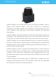
Introduction SLAMTEC Mapper is a new type of laser sensor introduced by SLAMTEC, which is different from traditional LIDAR. It has built-in functions of simultaneous localization and mapping (SLAM), and is suitable for many applications such as robot navigation and positioning, environmental mapping and hand-held measurement.
System Composition and Connection SLAMTEC Mapper professional kit includes LIDAR sensors and data processing units. Users only need to connect to 5V DC power supply, then with Ethernet or WiFi SLAMTEC Mapper can be easily communicated. SLAMTEC Mapper professional kit supports DC power supply for DC sockets. Users can obtain real-time map and pose data generated by SLAMTEC Mapper through WiFi signal, and can also realize high-speed and stable data path through Ethernet interface.
Figure 1-2 Block Diagram of working principle of SLAMTEC Mapper Driven by the motor mechanism, the SLAMTEC Mapper's ranging core will rotate clockwise to achieve 360-degree omni-directional map of the surrounding environment. * Note: There is no direct connection and disproportionate relationship between the sensor mapping and the environmental schematic here. This is for illustrative purposes only.
Safety and Scope SLAMTEC Mapper uses a low-power infrared laser as the emission source and is driven by a modulated pulse mode. The laser can only launch in a very short time. Class I Therefore, it can ensure the safety of humans and pets, and can meet the Class I level of laser safety standards. The product conforms to 21 CFR 1040.10 and 1040.11, except for deviation according to Laser Notice No. 50 of 24 June 2007.
Specification Measurement Performance For Model M2M1 Only Item Detail Parameter Distance Range1 The largest distance measured by radar 40m Sample Rate Laser points sampled per second by radar 9200 Hz Maximum Area Maximum Mapping Area 300m * 300m 2 Mapping resolution Maximum moving speed Maximum rotation speed 0.05m Maximum Linear Speed of Product Mobility Maximum angular velocity of product rotation 2 m/s TBD Accuracy < 0.
Optical Window To make SLAMTEC Mapper working normally, please ensure proper space to be 5 left for its emitting and receiving laser lights when designing the host system . The obscuring of the host system for the ranging window will impact the performance and resolution of SLAMTEC Mapper. If you need cover the SLAMTEC Mapper with translucent materials or have other special needs, please contact SLAMTEC about the feasibility.
Communication interface SLAMTEC Mapper uses a separate 5V DC power supply. Through simple plugand-play functions, users can connect it to mobile devices such as mobile phones to create an integrated portable measurement scheme.
For Model M2M1 Only Item Unit Min Typical Max Remark Power Voltage V 4.8 5 12 If the voltage exceeds the max value, it may damage the core Power Voltage Ripple mV - 20 50 High ripple may cause the core working failure. System Start Current mA 1400 1500 1600 TBD 40 50 5V Power,power off TBD 750 1300 5V Power,power on Power Current mA Figure 2-7 SLAMTEC Mapper Power Supply Specification Data communication interface SLAMTEC Mapper communicates with WiFi over Ethernet.
Self-protection and Status Detection When SLAMTEC Mapper is not working properly, users can get the working status of the system through SDK health data acquisition interface, and try to restart SLAMTEC Mapper to restore work. 11 / 15 Copyright (c) 2009-2013 RoboPeak Team Copyright (c) 2013-2019 Shanghai Slamtec Co., Ltd.
SDK and Support In order to facilitate users to use SLAMTEC Mapper for product development and accelerate the development cycle, SLAMTEC provides RoboStudio, a software for robot management and development, which can be debugged graphically through network connection. In addition, SDK development kit which can run on X86 windows, x86 Linux, arm Linux and other platforms is also provided to users. For specific information, please contact SLAMTEC.
Mechanical Dimensions The mechanical dimensions of the SLAMTEC Mapper are shown as below: Figure 5-1 SLAMTEC Mapper Mechanical Dimensions Note: the 4*M2.5 screws in the LIDAR bottom should be no longer than 6mm, or the internal module would be damaged. 13 / 15 Copyright (c) 2009-2013 RoboPeak Team Copyright (c) 2013-2019 Shanghai Slamtec Co., Ltd.
Revision history Date Version Description 2019-7-19 1.0 Initial version for SLAMTEC Mapper 1.1 Fix formatting errors and adjust table sequence. Correct the duty cycle in Table 2-2. Data for adding weights in Table 2-9. 2019-11-29 14 / 15 Copyright (c) 2009-2013 RoboPeak Team Copyright (c) 2013-2019 Shanghai Slamtec Co., Ltd.
Appendix Image and Table Index FIGURE 1-1 SLAMTEC MAPPER SYSTEM COMPOSITION.............................................................................................. 4 FIGURE 1-2 BLOCK DIAGRAM OF WORKING PRINCIPLE OF SLAMTEC MAPPER............................................................... 5 FIGURE 1-3 THE OBTAINED ENVIRONMENT MAP FROM SLAMTEC MAPPER ................................................................. 5 FIGURE 2-1 SLAMTEC MAPPER PERFORMANCE .............................................