RPLIDAR A1 2018-03-23 rev.1.1 Low Cost 360 Degree Laser Range Scanner Introduction and Datasheet Model: A1M8 www.slamtec.com Shanghai Slamtec.Co.
Contents CONTENTS ................................................................................................................................................... 1 INTRODUCTION ......................................................................................................................................... 3 SYSTEM CONNECTION ........................................................................................................................................ 3 MECHANISM ........................
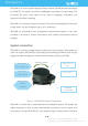
Introduction RPLIDAR A1 is a low cost 360 degree 2D laser scanner (LIDAR) solution developed by SLAMTEC. The system can perform 360degree scan within 12 meter range. The produced 2D point cloud data can be used in mapping, localization and object/environment modeling. RPLIDAR A1’s scanning frequency reached 5.5 hz when sampling 360 points each round. And it can be configured up to 10 hz maximum. RPLIDAR A1 is basically a laser triangulation measurement system.
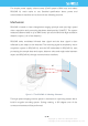
The simple power supply schema saves LIDAR system’s BOM cost and makes RPLIDAR A1 much easier to use. Detailed specification about power and communication interface can be found in the following sections. Mechanism RPLIDAR is based on laser triangulation ranging principle and uses high-speed vision acquisition and processing hardware developed by SLAMTEC. The system measures distance data in up to 8000 times’ per second and with high resolution distance output (<1% of the distance).
*Note:The LIDAR scan image is not directly relative to the environment showed here. Illustrative purpose only. Figure 1-3 The Obtained Environment Map from RPLIDAR A1 Scanning Safety and Scope RPLIDAR A1 system use a low power (<5mW) infrared laser as its light source, and drives it using modulated pulse. The laser emits in a very short time frame which can make sure its safety to human and pet and reach Class I laser safety standard.
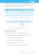
sampling data continuously. Host systems can configure output format and stop RPLIDAR A1 by sending stop command. If you need detailed data format and communication protocol, please contact with SLAMTEC.
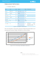
Specification Measurement Performance o For Model A1M8 Only Item Distance Range Angular Range Distance Resolution Angular Resolution Sample Duration Sample Frequency Scan Rate Unit Min Typical Max Meter(m) TBD 0.15 - 12 TBD Degree n/a 0-360 n/a mm n/a <0.5 <1% of the distance n/a Degree n/a ≤1 n/a Millisecond(ms ) n/a 0.5 n/a Hz n/a 4000 8000 Hz 1 5.5 10 Comments White objects <1.5 meters All distance range* 5.
Laser Power Specification o For Model A1M8 Only Item Unit Laser wavelength Nanometer(nm) Laser power Milliwatt (mW) Pulse length Microsecond(us) Min Typical Max Comments 775 785 795 TBD 3 5 Infrared Light Band Peak power TBD 110 300 Figure 2-3 RPLIDAR A1 Optical Specification Communication interface RPLIDAR A1 uses 3.3V-TTL serial port (UART) as the communication interface. Other communication interface such as USB can be customized according to customer’s requirement.
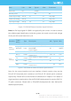
Item Unit Min Typical Max Comments Band rate bps - 115200 - Working mode - - 8N1 - 8n1 Output high voltage Volt (V) 2.9 - 3.5 Logic High Output low voltage Volt (V) - - 0.4 Logic Low Input high voltage Volt (V) 1.6* - 3.5 Logic High Input low voltage Volt (V) -0.3 - 0.4 Logic Low Figure 2-5 RPLIDAR External Interface Signal Definition Note: the RX input signal of A1M8 is recognized by the current.
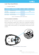
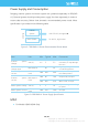
Power Supply and Consumption Ranging scanner system and motor system are powered separately in RPLIDAR A1. External system should provide power supply for them separately in order to ensure data accuracy. Below chart showed a recommended power mode. More specification is provided in the following table. RPLIDAR Scanner System 4.9V-5.
Item Unit Weight Gram (g) Temperature range Degree Celsius (oC) Min Typical Max TBD 190 TBD 0 TBD 45 Comments Figure 2-9 RPLIDAR A1 MISC Specification 11 / 16 Copyright (c) 2009-2013 RoboPeak Team Copyright (c) 2013-2016 Shanghai Slamtec Co., Ltd.
Self-protection and Status Detection To make sure RPLIDAR A1’s laser always working in the safety range (<5mW) and avoid any other damage caused by device, RPLIDAR A1 comes with laser power detection and sensor healthy check feature. RPLIDAR A1 will shut down the laser and stop working when any of below errors has been detected.
SDK and Support SLAMTEC provides debug GUI tool and SDK (available for Windows, x86 Linux and Arm Linux) to speed up the product development for users. Please contact SLAMTEC for detail information. Figure 4-1 the Debugging GUI of RPLIDAR A1 13 / 16 Copyright (c) 2009-2013 RoboPeak Team Copyright (c) 2013-2016 Shanghai Slamtec Co., Ltd.
Mechanical and Customization Options To facility customer’s integration, RPLIDAR A1’s structure is designed to decouple the core ranging system and fixed platform which can be customized. The part marked red in the below figure is the fixed platform that can be customized according to customer requirement. Figure 5-1 The fixd platform of RPLIDAR A1 The RPLIDAR A1-A1M8 assemble size showed below: GH1.
Revision History Date Description 2013-3-13 Initial draft 2013-5-16 1. Updated the laser class information 2. Updated motor voltage range 3. Updated size chart according to Rev1.
Appendix Image and Table Index FIGURE 1-1 RPLIDAR A1 SYSTEM COMPOSITION ............................................................................................... 3 FIGURE 1-2 THE RPLIDAR A1 WORKING SCHEMATIC ......................................................................................... 4 FIGURE 1-3 THE OBTAINED ENVIRONMENT MAP FROM RPLIDAR A1 SCANNING ............................................. 5 FIGURE 1-4 THE RPLIDAR A1 SAMPLE POINT DATA INFORMATION .....................................