2018-03-08 rev.1.1 RPLIDAR Low Cost 360 Degree Laser Range Scanner Interface Protocol and Application Notes Applied to RPLIDAR A1 & A2 www.slamtec.com Shanghai Slamtec.Co.
Contents CONTENTS ................................................................................................................................................... 1 OVERVIEW ................................................................................................................................................... 3 SDK AND DEMO PROGRAM .............................................................................................................................. 3 PROTOCOL BASICS ...................
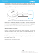
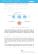
Overview The host system communicates with RPLIDAR core system via the TTL UART serial interface. Based on the communication protocol defined in this document, the host system can retrieve the scan data, the device status, the health information etc. and manipulate RPLIDAR’s working mode.
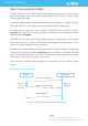
Protocol Basics Basic Communication Mode The RPLIDAR uses a non-textual binary data packet based protocol to communicate with host systems. And all the packets transmitted on the interface channel share uniform packet formats. A communication session is always initialized by a host system, i.e. a MCU, a PC, etc. RPLIDAR itself won’t send any data out automatically after powering up. If a data packet is sent from host systems to RPLIDARs, such a packet is called a Request.
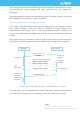
Host system should prevent sending extra request packets if the RPLIDAR is busy with handing the current request and hasn’t replied to the host system yet. Otherwise, these extra request packets will be discarded by the RPLIDAR’s protocol stack and the RPLIDAR will not have any chance to handle it. Single Request-Multiple Response Modes This mode is used when the RPLIAR is asked to perform the scan operation.
responses mode, the RPLIDAR will continue to handle the request which has interrupted it. The request packets sent by the host system during the multiple responses mode will be cached by the RPLIDAR’s protocol stack. After leaving the multiple responses mode, RPLIDAR will handle the cached request. Single Request-No Response For requests like STOP, RESET Core, RPLIDAR uses the single request – no response mode since there is no need to reply to the host system.
A fixed 0xA5 byte is used for each request packet, RPLIDAR uses this byte as the identification of a new request packet. An 8bit (1byte) command field must follow the start flag byte. If the current request carries extra payload data, an 8bit (1byte) payload size field is required to be transmitted after sending the command field and then follows the payload data. After the payload data has been transmitted, an 8bit (1byte) checksum field calculated from the previous sent data should be transmitted.
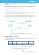
RPLIDAR Host System Request #1 Response Descriptor Data Response 2 Request #2 … Figure 2-5 Response Packets Sent during a Single Request-Single Response Mode RPLIDAR Host System Request #1 Response Descriptor Data Response Data Response Data Response … 2 Request #2 … Figure 2-6 Response Packets Sent during a Single Request-Multiple Response Mode The format of response descriptors is depicted in the following figure.
A response descriptor uses fixed two bytes’ pattern 0xA5 0x5A for the host system to identify the start of a response descriptor. The 30bit Data Response Length field records the size of a single incoming data response packet in bytes. (All the incoming data response packets within a request/response session should have the same format and length). The 2bits Send Mode field describes the request/response mode of the current session.
Working State and Mechanism Major Working States and Transition Conditions RPLIDAR has the following 4 major states: Idle, Scanning, Request Processing and the Protection Stop state.
status. But the host system cannot ask the RPLIDAR to perform scan operations unless the host system send a Reset request to reboot the RPLIDAR core system. Scanning Status RPLIDAR always checks the motor rotation status when working in the scanning state. Only when the motor rotation speed becomes stable, RPLIDAR will start taking distance measurement and sending out the result data to the host system.
Request and Response Data Requests Overview All the available requests are listed in the below table. Their detailed descriptions are given in the following sections.
Next request 25 A5 Host System RPLIDAR A5 … ≥1m s Figure 4-2 The Timing Sequence of a STOP Request RPLIDAR Core Reset(RESET) Request Request Packet: A5 40 Host systems can make RPLIDAR core to reset (reboot) itself by sending this request. A reset operation will make RPLIDAR revert to a similar state as it has just been powered up. This request is useful when RPLIDAR has entered the Protection Stop state.
Request Packet: A5 20 Response Descriptor: A5 5A Response Mode: 05 Multiple 00 40 00 81 Data Response Length: 5 bytes RPLIDAR, except for the RPLIDAR that is in the Protection Stop State, will enter the scanning state once it receives this request from a host system. Each measurement sample result will be sent out using an individual data response packet. If the RPLIDAR has been in scanning state already, it will stop the current measurement sampling and start a new round of scanning.
RPLIDAR encapsulates each measurement sample into a data response packet with the format showed in the above figure and send the packet out. The descriptions of every field within the packet are listed in the following table: Field Name Description Examples / Notes S Start flag bit of a new scan When S is set to 1, the current and incoming packets belong to a new 360o scan. ̅ 𝑺 Inversed start flag bit, always has 𝑆ҧ = Can be used as a data check bit.
θ [0,360) Interface Lead Figure 4-7 Angle and Distance Value Geometric Definition for RPLIDAR A2 series Data transmission order: A5 a new request 20 A5 … 360o scan A5 5A 05 00 00 40 … Host System RPLIDAR S=1 … a new scan 81 Figure 4-8 The Communication Status after Host System Sending a SCAN Request 16 / 32 Copyright (c) 2009-2013 RoboPeak Team Copyright (c) 2013-2017 Shanghai Slamtec Co., Ltd.
Express Scan(EXPRESS_SCAN) Request and Response Request Packet: A5 82 05 00 00 00 00 Response Descriptor: A5 5A 54 00 00 40 82 Response Mode: Multiple 00 Data Response Length: 22 84 bytes RPLIDAR will enter the measurement sampling mode once it receives the express scan(EXPRESS_SCAN) request. Different from the scan(SCAN) request, this request will make RPLIDAR work at the sampling rate as high as it can be.
0 8 Byte Offset +0 working_mode 0 8 +1 Reserved 0 8 Reserved +2 0 8 Reserved +3 0 8 +4 Reserved Figure 4-9 Format of a RPLIDAR Express Scan Data Request Packet The descriptions of every field within the above data are listed in the following table: Field Name Description Examples/Notes working_mode The field only supports for The other parameters in the scan standard scan mode currently, mode of RPLIDAR, set to 0. set to 0. Reserved Reserved field, set to 0.
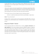
Format of the data response packets: RPLIDAR uses the following data response packet structure for responding the EXPRESS_SCAN request.
The descriptions of every field within the above packet are listed in the following table: Field Name Description sync1 Data packet start sync flag1. Always be 0xA sync2 Data packet start sync flag2. Always be 0x5 start_angle_q6 The reference value for the angle data in the current response packet. Stored with fix point number in q6 format and the unit is degree.
The following table describes the filed definition of the Cabin data. Field Definition Description Examples/Notes The distance data for the first and second measurement sampling. The unit is millimeter(mm) When the value is 0, the matched sampling point is invalid. The angular compensation value for the first and second measurement sampling. It uses fix point number in q3 format and the unit is degree. The top digit is sign bit. distance1 distance2 𝑑𝜃1 𝑑𝜃2 The first sampling time is before the second.
Data Processing of the Express Scan Data By compressing the redundant data, the data response packet used in express scan mode makes it possible to send the 4khz sampling data via the original 115200bps bandwidth communication link. For this reason, the host system needs extra data recovery logic to get valid measurement data. When working in express scan mode, the measurement sampling data is stored in the cabin structural body with two sets as unit.
The actual included angle 𝜃𝑘 of any measurement sampling point 𝐶𝑘 can be calculated out via the following formula: 𝜃𝑘 = 𝜔𝑖 + 𝐴𝑛𝑔𝑙𝑒𝐷𝑖𝑓𝑓(𝜔𝑖 , 𝜔𝑖+1 ) ⋅ 𝑘 − 𝑑𝜃𝑘 32 The function 𝐴𝑛𝑔𝑙𝑒𝐷𝑖𝑓𝑓(𝜔𝑖 , 𝜔𝑖+1 ) in the above formula is defined as below: 𝜔𝑖+1 − 𝜔𝑖 , AngleDiff(𝜔𝑖 , 𝜔𝑖+1 ) = { 360 + 𝜔𝑖+1 − 𝜔𝑖 , 𝜔𝑖 ≤ 𝜔𝑖+1 𝜔𝑖 > 𝜔𝑖+1 Response descriptor flag S: After entering express scan mode, the first sent data response packet always has the S flag set to 1.
Get Device Info (GET_INFO) Request and Response Request Packet: A5 50 Response Descriptor: A5 5A 14 00 Single Response Mode: 00 00 04 Data Response Length: 20 bytes RPLIDAR will send out its device information (e.g. serial number, firmware/hardware version) to the host system once it receives this request.
Field Name Description Examples / Notes model RPLIDAR model ID The model ID of the RPLIDAR being used firmware_minor Firmware version number, the The decimal part of the version minor value part number firmware_major Firmware version number, the The integer part of the version major value part number hardware Hardware version number serialnumber[16] 128bit unique serial number When converting to text in hex, the Least Significant Byte prints first Figure 4-17 Field Definition of Device Info D
Get Device Health Status (GET_HEALTH) Request and Response Request Packet: A5 52 Response Descriptor: A5 5A 3 Single Response Mode: 00 00 00 06 Data Response Length: 3 bytes A host system can send the GET_HEALTH request to query RPLIDAR’s health state. If the RPLIDAR has entered the Protection Stop state caused by hardware failure, the related error code of the failure will be sent out.
Stop state. However, if RPLIDAR enters the Protection Stop state for several times, this may be a sign of some unrecoverable damage has occurred in RPLIDAR.
Application Notes Retrieving scanning data from an RPLIDAR It is recommended that a host system always follows the below sequence to enable RPLIDA’s scanning operation and retrieve the scanning data. Before sending a SCAN request, the host system should send a GET_HEALTH request in advance to query the RPLIDAR’s health status. In case RPLIDAR is in the Protection Stop state, the host system can send a RESET request to try to escape the Protection Stop state.
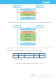
Calculate RPLIDAR Scanning Speed In most cases, there is no need for a host system to care about the actual RPLIDAR scanning speed. RPLIDAR ensures the precision of the measurement results using its build-in self-adaptive motor rotation speed detector. If an RPLIDAR is required to have a fixed scanning speed, the host system can control the motor speed using a PWM driver and based on the speed feedback provided by the algorithm described in this section.
∆T. The interval time represents how long the RPLIDAR has spent to perform a 360o scan. So the actual scan speed can be calculated using the following equation: RPM = 1 ∗ 60 ∆𝑇 The calculated value can be used as a feedback to control the motor speed. 30 / 32 Copyright (c) 2009-2013 RoboPeak Team Copyright (c) 2013-2017 Shanghai Slamtec Co., Ltd.
Revision History Date Description 2013-3-5 2014-1-25 2014-3-8 2015-8-21 2016-4-10 2016-5-4 2016-10-28 2017-05-15 2018-03-08 Initial vesion Modified related descriptions Added descriptions about the time requirement of sending request packet. Modified the incoherence in the context of GET_HEALTH Added descriptions for the RPLIDAR A2 newly added protocol Fixed a description bug Fixed a description bug in the EXPRESS_SCAN protocol section Release 1.
Appendix Image and Table Index FIGURE 1-1 THE COMMUNICATION BETWEEN RPLIDAR AND HOST SYSTEM ..................................................... 3 FIGURE 2-1 RPLIDAR REQUEST/RESPONSE MODES ............................................................................................ 4 FIGURE 2-2 RPLIDAR SINGLE REQUEST - MULTIPLE RESPONSE MODE .............................................................. 5 FIGURE 2-3 RPLIDAR SINGLE REQUEST-NO RESPONSE MODE ....................................................