SLAMWARE Modular Autonomous Robot Localization and Navigation Solution Datasheet 2016-05-09 rev.1.8 Shanghai Slamtec Co., Ltd. www.slamtec.
Contents CONTENTS .................................................................................................................................................................................... 1 1. INTRODUCTION ............................................................................................................................................................... 3 FUNCTION & FEATURE .................................................................................................................
1. Introduction SLAMWARE modular autonomous robot localization and navigation solution is the core control module developed by SLAMTEC. It is available for autonomous localization and navigation based on RPLIDAR and supports for communicating the navigation information via serial port and Ethernet bus. SLAMWARE modular autonomous robot localization and navigation solution implements the feature of map building, automatically path planning and motion controlling without extra calculating.
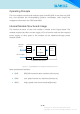
Operating Principle The core module controls and reads the plan from RPLIDAR in real time via LBUS bus, and calculate the corresponding position coordinates, then output the navigation information via CBUS and HBUS. Internal Module Structure & Usage The internal structure of the core module is shown as the figure below. The module requires the direct current supply of 5v to function well and the required power supply of other parts in the module can be obtained through power network inside.
2. Property Maximum Rating Item Range Power supply voltage Pin voltage Operating temperature range -0.5V ~+6.0V -0.3V ~Vsc+0.
3. Interfaces SLAMWARE CORE MODULE is connected via the standard MINI PCIE 52 pin. Pin Definition No. Name 1 NC 3 GND 5 NC 7 NC 9 GND 11 NC 13 NC 15 GND 17 NC 19 NC 21 23 25 27 29 31 33 35 37 GND ETH_RXETH_RX+ ETH_RREF GND ETH_TXETH_TX+ ETH_TREF GND 39 NC 41 NC 43 GND 45 LPWM 47 49 51 LTX LRX nL5VEN Description Floating pin. Please set the pin not connected and not receiving any signal. System ground wires Floating pin.
2 5V System power supply +5V。 4 GND 6 NC 8 10 12 14 16 18 CBUSY CRX CTX GND nCCMD GND 20 NC 22 NC 24 26 28 MLED GND 5V 30 NC 32 NC 34 GND 36 NC 38 NC 40 GND 42 NC 44 NC 46 NC 48 50 52 5V GND 5V System ground wires Floating pin. Please set the pin not connected and not receiving signal. CBUS busy signal. OD output. High effective. CBUS data receiving port CBUS data sending port System ground wires CBUS data interrupt signal. Negedge effective. OD control required.
Time Sequence All the communication interfaces of SLAMWARE core module such as LBUS, CBUS, HBUS, etc. meet the requirement of international standard UART and ETH Typical Circuit SLAMWARE CORE 5V RJ45 5V GND PWR HBUS LBUS CBUS 5.
4. Mechanical Design SLAMWARE core module mechanical configuration meets the standard of MINI PCIE’s mechanical dimensions. SLAMWARE CORE MODULE is 4 mm thick both in the top and bottom, please make sure enough space to be set aside and heat output channel to be designed properly. The recommended MINI PCIE card connector for SLAMWARE CORE MODULE is MOLEX Edge Card Connector, PN:67910-9000, (0.80mm Pitch, 9.00mm Height, PCI Express* Mini Card, 52 Circuit, Right Angle, Surface Mount, 0.
Figure 4-2 SLAMWARE Core Module’s Design Parameter 10 / 13 Copyright (c) 2009-2013 RoboPeak Team Copyright (c) 2013-2016 Shanghai Slamtec Co., Ltd.
5. Contact Us The product is designed and produced by SLAMTEC and our homepage is: http://www.slamtec.com If you have any questions or suggestions, please contact us via the following support email: support@slamtec.com 11 / 13 Copyright (c) 2009-2013 RoboPeak Team Copyright (c) 2013-2016 Shanghai Slamtec Co., Ltd.
6. Revision History Date Version Description 2015-1-5 2015-9-9 2015-10-9 2015-10-15 2015-12-30 2015-01-25 2016-05-09 0.1 0.2 0.3 0.4 0.5 0.6 1.8 Initial version Add typical figure frame diagram Delete obsolete chapters and update contents Add recommended card connector model for MINI PCIE Polish up the text and remove the logo of RoboPeak Add 5v power supply control pin for RPLIDAR core Updated the layout 12 / 13 Copyright (c) 2009-2013 RoboPeak Team Copyright (c) 2013-2016 Shanghai Slamtec Co.
Appendix Image and Table Index FIGURE 1-1 SLAMWARE CORE MODULE INTERNAL STRUCTURE........................................................................ 4 FIGURE 2-1 SLAMWARE CORE MODULE INTERNAL STRUCTURE........................................................................ 5 FIGURE 2-2 SLAMWARE CORE MODULE ELECTRICAL CHARACTERISTICS ........................................................... 5 FIGURE 2-3 SLAMWARE CORE MODULE TIME RESPONSE ................................................................