
Datasheet


6 / 13
Copyright (c) 2009-2013 RoboPeak Team
Copyright (c) 2013-2016 Shanghai Slamtec Co., Ltd.
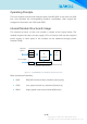
SLAMWARE CORE MODULE is connected via the standard MINI PCIE 52 pin.
Pin Definition
No.
Name
Description
1
NC
Floating pin. Please set the pin not connected and not receiving any
signal.
3
GND
System ground wires
5
NC
Floating pin. Please set the pin not connected and not receiving any
signal.
7
NC
Floating pin. Please set the pin not connected and not receiving any
signal.
9
GND
System ground wires
11
NC
Floating pin. Please set the pin not connected and not receiving any
signal.
13
NC
Floating pin. Please set the pin not connected and not receiving any
signal.
15
GND
System ground wires
17
NC
Floating pin. Please set the pin not connected and not receiving any
signal.
19
NC
Floating pin. Please set the pin not connected and not receiving any
signal.
21
GND
System ground wires
23
ETH_RX-
HBUS Ethernet RXI-
25
ETH_RX+
HBUS Ethernet RXI+
27
ETH_RREF
HBUS Ethernet receiving termination voltage
29
GND
System ground wires
31
ETH_TX-
HBUS Ethernet RXI-
33
ETH_TX+
HBUS Ethernet RXI+
35
ETH_TREF
HBUS Ethernet receiving termination voltage
37
GND
System ground wires
39
NC
Floating pin. Please set the pin not connected and not receiving any
signal.
41
NC
Floating pin. Please set the pin not connected and not receiving any
signal.
43
GND
System ground wires
45
LPWM
LBUS RPLIDAR motor PWM speed control signal. Motor speed of
HRPWM when duty ratio is proportional to output torque.
47
LTX
LBUS RPLIDAR data sending port. RPLIDAR RX connection required.
49
LRX
LBUS RPLIDAR data receiving port. RPLIDAR TX connection required.
51
nL5VEN
Power supply control pin for LBUS RPLIDAR core.
3. Interfaces