
Installation & Operating Manual


Bobcat Models B-120A and B-200A
8
VENT AND AIR INTAKE MATERIALS
The vent and air intake system for direct or non-direct vent
installation must be 3” diameter PVC/CPVC schedule. 40 pipe,
or UL listed single wall 3” diameter AL29-4C* stainless steel
material. The following manufacturers’ systems are approved for
use within a specified minimum and maximum equivalent vent
length in this manual.
When joining the various components of the listed stainless
steel vent systems, the manufacturers’ instructions should be
closely followed to insure proper sealing. Use sealant specified
by vent system manufacturer for sealing of pipe and fittings, if
required. When joining the PVC/CPVC pipe and fittings, follow
the instructions provided in this manual. All connections must
be liquid and pressure tight. DO NOT use galvanized flue pipe
or any plastic-type materials other than CPVC Schedule 40.
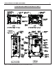
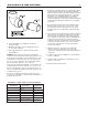
The integral adapters on the boiler are designed to accommo-
date either PVC/CPVC Schedule 40 pipe or the listed stainless
steel vent systems. These adapters have built-in sealing rings,
so no additional sealant is required. Make sure the pipes are
round and burr-free, and push down into the appropriate step
of the adapter, until snug. (See Figure 5). Apply liquid soap to
the outer end of the pipes for easy insertion.
PVC/CPVC PIPE GENERAL ASSEMBLY METHOD
The following are the recommended methods for cutting,
cleaning and connecting PVC and CPVC pipes:
1. When laying out the piping system, work from the boiler
vent and air intake adapter to the point of outside
termination.
2. Cut the pipes to the required lengths, and pre-assemble
the entire system, before sealing. Disassembly after
sealing, to make any corrections, will not be possible.
3. Once the pre-assembled PVC/CPVC piping system is
verified to be of the proper length pipe and fitting
orientation, begin disassembling and preparing the pipes
and fittings for the sealing process. This can be done
section by section, or the complete vent and air intake
system can be disassembled. It is recommended to mark
the various parts, before complete disassembly, to
eliminate the possibility of errors during re-assembly.
4. De-burr the inside and outside of every PVC/CPVC pipe, to
ensure that they engage fully into the fittings, and flow is
not compromised. A small chamfer on the outside of each
pipe can particularly aid in the final assembly process.
5. Wipe or knock out any debris from inside the PVC or
CPVC pipe, which may have accumulated there from the
cutting process or storage. Debris can cause operational
problems with the boiler combustion components.
6. Thoroughly clean the outside ends of each pipe, and the
inside of each fitting. The surfaces must be dry for the
sealing agents to work properly. Handle the prepared pipe
lengths away from the cleaned ends, and handle the
cleaned fittings, from the outside, to avoid contamination.
7. Re-assembly of the PVC or CPVC pipe should be done in
sections, to avoid the primer and cement drying before the
parts are engaged.
8. For each joint, first apply a coat of primer to the outside
sealing surface of the pipe and the inside sealing surface of
each fitting. Use only the primer type that is specified for
either the PVC or CPVC pipe that is being utilized.
9. Before the primer dries, apply a coat of cement over it. A
second coat of cement can be applied, if necessary, but
must be done quickly and in a manner that avoids
unnecessary build-up that would cause obstruction inside
the system. Use only the cement type that is specified for
either the PVC or CPVC pipe that is being utilized.
10. Before the cement dries, insert the pipe into the fitting. A
slight twisting motion while pushing the pipe into the fitting
will aid in distributing the cement evenly and ensuring the
parts fully engage.
11. Quickly wipe the excess cement from the outside areas of
the joint. Discard any rags used to avoid later getting the
cement on hands, clothes and equipment.
VENT AND AIR INTAKE RESTRICTIONS
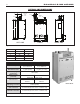
1. Maximum allowed equivalent vent and air intake length for
all of the approved vent and air intake materials is 100 feet
for B-120A and 50 feet for B-200A.
2. Equivalent of vent or air intake length is sum of the
straight pipe lengths and equivalent length of elbows as
shown in the table on this page.
Heat-Fab. Inc. Saf-T Vent Not Required
EZ Seal
ProTech System, FasNSeal Not Required
Inc.
Flex-L StaR-34 GE-IS806
International, Inc.
Z-Flex, Inc. Z-Vent GE, RTV 106
N/A PVC pipe, PVC primer
Schedule 40 and cement
N/A CPVC pipe, CPVC primer
Schedule 40 and cement
*AL29-4C is a registered Trademark of Allegheny Ludlum Corp
Manufacturer
Type/System
Sealant
Figure 5. Vent and Air Intake Pipe installation into Boiler
Adapter.