
Install Instructions

Slant Fin Corp. │ Installation and Operation Instructions CHS Series
66
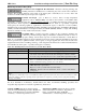
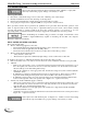
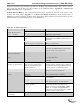
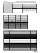
Table 15-1 Troubleshooting Chart
PROBLEM
POSSIBLE CAUSE
CORRECTIVE ACTION
Hold 65 – Interrupted Air
Switch OFF
Hold 66 – Interrupted air
switch ON
Hold 67 – ILK OFF
Low Water Condition
Check operation of internal LWCO.
External Limit Tripped
Indication that an external limit (wired to “LIM”)
is open. Not a problem with boiler, check
external limit.
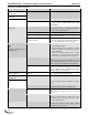
Lockout or Hold 79 – Outlet
High Limit
CH or DHW settings
Check if CH and/or DHW setpoint temperature
plus off hysteresis exceed “High limit” setpoint –
factory setting = 200°F (93°C).
CH or DHW pump problem
See "Inoperative CH or DHW pump" below.
Incorrect “Outlet high limit” setting
Increase “Outlet high limit” setting; maximum
setting = 200°F (93°C).
Incorrect “Outlet high limit
response” setting
Unless deemed unacceptable by local installation
codes, the “Outlet high limit response” should be
set to “recycle and hold” to prevent lockout.
Lockout or Hold 81 – Delta T
limit
OR
Appliance making banging or
hissing sounds
Insufficient water flow
Check Fuse "B"
Check appliance pump.
Ensure plumbing is correct. Refer to Section
10.0 System Piping. Check that water pressure
is at least 15PSI.
Boiler heat transfer surfaces may be fouled
with scale or magnetite. Clean with Fernox
DS-40 Descaler and Cleanser. See Table 10-1.
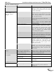
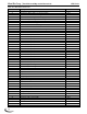
Lockout 82 – Stack limit
Dirty heat exchanger
Inspect and if required clean the combustion
chamber and/or heat exchanger. Refer to Section
14.0 Annual Maintenance and Inspection and
Section 10.0 Boiler and Heating System Piping.
Incorrect “Stack limit setpoint”
Unless installed in Canada with PVC exhaust
venting, set “Stack limit setpoint” to maximum
setting of 220ºF (104ºC). In Canada PVC exhaust
venting is limited to 149ºF (65ºC).
Lockout 85 – Inlet/Outlet
Inversion Limit
Pump flowing in the wrong
direction
Ensure water circulation through the boiler is in
the correct direction, see Figure 10-1.
Lockout or Hold 88 – Outlet
T Rise limit
Insufficient water flow
See Lockout 81.
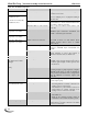
Hold 91– Inlet sensor fault
Sensor disconnected
Check sensor connection located on the bottom of
the heat exchanger. Check connection on control
board.
Faulty sensor
Check resistance of sensor and compare to
thermistor resistance chart, see Table 15-2.
Hold 92 – Outlet sensor fault
Sensor disconnected
Check sensor connection located on the top of the
heat exchanger. Check connection on control
board.
Faulty sensor
Check resistance of sensor and compare to
thermistor resistance chart, see Table 15-2. (Note
the Outlet sensor incorporates two sensors, check
resistance individually.)
Hold 95 – Stack sensor fault
Sensor disconnected
Check sensor connection located at the bottom of
the flue pipe inside the boiler cabinet. Check
connection on control board.