This manual must be left with owner and should be hung on or adjacent to the boiler for reference. ® C US HIGH EFFICIENCY FIRE TUBE CONDENSING GAS BOILER MODELS CHS-85 through CHS-399 INSTALLATION AND OPERATING INSTRUCTIONS IMPORTANT READ ALL OF THE FOLLOWING WARNINGS AND STATEMENTS BEFORE READING THE INSTALLATION INSTRUCTIONS DANGER ! Danger Sign: Indicates a hazardous situation which, if not avoided, will result in serious injury or death.
Slant Fin Corp. │ Installation and Operation Instructions CHS Series Read Before Proceeding If you do not follow these instructions exactly, a fire or explosion may result causing property damage, serious injury or death. FOR YOUR SAFETY, READ BEFORE OPERATING_ A) This boiler does not have a pilot. It is equipped with an ignition device which automatically lights the burner. Do not try to light the burner by hand. B) BEFORE OPERATING smell all around the boiler area for gas.
CHS Series Installation and Operation Instructions │ Slant Fin Corp. 1.0 INTRODUCTION General Installation Requirements The installation of your Slant/Fin CHS gas boiler must conform to the requirements of this manual, your local authority, and the National Fuel Gas Code ANSI Z223.1 and or CAN/CGA B149 Installation Codes. Where required by the Authority, the installation must conform to the standard for “Controls and Safety Devices for Automatically Fired Boilers ANSI/ASME CSD-1.
Slant Fin Corp. │ Installation and Operation Instructions CHS Series Failure to use the appropriate Natural to LP Conversion Kit and Orifice when operating the CHS with Propane will result in extremely dangerous burner operation leading to property damage, serious injury or death. Refer to section titled ATTENTION: LIQUEFIED PETROLEUM (LP) PROPANE for applicable conversion kit and LP orifice numbers. ATTENTION: LIQUEFIED PETROLEUM (LP) PROPANE The CHS boiler is factory set to operate with Natural Gas.
CHS Series Installation and Operation Instructions │ Slant Fin Corp.
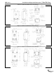
Slant Fin Corp. │ Installation and Operation Instructions CHS Series 2.0 SPECIFICATIONS Table 2-1 CHS Specifications DESCRIPTION CHS-85 CSA Input Modulation 1,4 17-85 [MBH] DOE Heating Capacity 1,2 78 [MBH] CHS-110 21.6-108 31-155 31-175 31-200 31-250 79.8-299 79.8-399 99 144 163 185 230 278 380 125 141 160 199 239 330 95 95 95 95 94 95.4 Net I=B=R Rating 1,2 68 86 [MBH] DOE AFUE2 [%] 95 95 Water Connections – NPT 1 (Male) [in.] Gas Connection - NPT, in.
CHS Series Installation and Operation Instructions │ Slant Fin Corp.
Slant Fin Corp. │ Installation and Operation Instructions CHS Series 3.0 BOILER LOCATION In all cases, the CHS boiler must be installed indoors in a dry location where the ambient temperature must be maintained above freezing and below 100F [38C]. All boiler components must be protected from dripping, spraying water, or rain during operation and servicing.
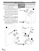
CHS Series Installation and Operation Instructions │ Slant Fin Corp. Figure 3-1 Closet Installation, Minimum Clearances (Model CHS 85-110 Shown) Min. 1” clearance for hot water and vent pipes Top = 12” Top ventilation opening Max. 6” below ceiling / top Ventilation air opening 2 1in per 1000 Btu/hr, 2 min. 100in Removable surface / closet door Ventilation air opening 2 1in per 1000 Btu/hr, 2 min. 100in Bottom ventilation opening Max.
Slant Fin Corp. │ Installation and Operation Instructions CHS Series Figure 3-2 Wall Mounting Instructions While leaving the Upper bracket (A) intact, remove the Wall-mount bracket (B) attached to the bottom-back of the appliance. Save the mounting hardware for Step 4.
CHS Series Installation and Operation Instructions │ Slant Fin Corp. 4.0 GENERAL VENTING The CHS boiler is certified as a “Category IV” boiler requiring a “Special Venting System” designed for pressurized venting. The Exhaust Vent must be piped to the outdoors, using the vent materials and rules outlined in this section. Under no conditions may this unit vent gases into a masonry chimney, unless it is vacant, and utilizes the approved venting material and rules described in this section.
Slant Fin Corp. │ Installation and Operation Instructions CHS Series and 6 in. from the front of the appliance. The opening shall directly communicate with the outdoors or shall communicate through a vertical or horizontal duct to the outdoors or spaces that freely communicate with the outdoors (see Figure 4-1e) and shall have a minimum free area of the following: a. 1 in.2/3000 Btu/hr of the total input rating of all appliances located in the enclosure, and b.
CHS Series Installation and Operation Instructions │ Slant Fin Corp. Combustion Air-inlet Contamination Be careful not to locate the air-inlet termination in an area where contaminants can be drawn in and used for combustion. Combustion air containing dust, debris or air-borne contaminants will drastically increase the required maintenance and may cause a corrosive reaction in the Heat Exchanger which could result in premature failure, fire, serious injury, or death.
Slant Fin Corp.
Installation and Operation Instructions │ Slant Fin Corp.
Slant Fin Corp. │ Installation and Operation Instructions Table 4-2 CPVC Vent Pipe Transition Piece (used when venting with PVC) Model No. Vent Pipe Size CPVC Transition Vent Pipe Length CHS 85-110 3” Minimum 5” [127 mm] CHS 155-250 3” Minimum 5” [127 mm] CHS 300-399 4” Minimum 5” [127 mm] Table 4-3 Appliance Adapters for Polypropylene and Stainless Steel Venting Model No.
Installation and Operation Instructions │ Slant Fin Corp. CHS Series Mandatory Pre-commissioning Procedure for Plastic Venting (PVC or CPVC) Do not apply power to the boiler prior to Step 4 in the Mandatory Pre-commissioning Procedure for Plastic Venting. 1) Working with the power turned off to the boiler, completely install the vent and air intake system, securely cementing joints together. If possible, allow primers/cements to cure for 8 hours before firing the burner.
Slant Fin Corp. │ Installation and Operation Instructions CHS Series Termination Options – Direct Vent Installation The venting system of the CHS may be terminated using field supplied piping to construct a “Two-Pipe” termination, see Figures 4-3a, 4-4a, 4-4d, 4-5a, 4-6a and 4-6d; alternatively the venting may be terminated using a factory kit selected from Table 4-6.
Installation and Operation Instructions │ Slant Fin Corp. CHS Series Sidewall Venting Options – Direct Vent Installation Figure 4-3(a) Two-pipe Termination (Sidewall) Figure 4-3(b) IPEX Low Profile Termination (Sidewall) Location of exhaust and air-inlet connections vary between models, see Figure 4-2. (model CHS 85-110 shown) Location of exhaust and air-inlet connections vary between models, see Figure 4-2.
Slant Fin Corp. │ Installation and Operation Instructions CHS Series Roof Venting Options – Direct Vent Installation Figure 4-4(a) Two-pipe Termination (Roof) Figure 4-4(b) IPEX Concentric Termination (Roof) Location of exhaust and air-inlet connections vary between models, see Figure 4-2. (model CHS 85-110 shown) Location of exhaust and air-inlet connections vary between models, see Figure 4-2.
Installation and Operation Instructions │ Slant Fin Corp. CHS Series Sidewall Termination Details – Direct Vent Installation Figure 4-5(a) Two-Pipe Termination (Sidewall) Figure 4-5(b) IPEX Concentric Termination (Sidewall) Horizontal 4-12” or greater than 36” Refer to documentation included with termination kit for complete installation instructions. Exhaust Exhaust Exhaust Air-inlet Vertical Min.
Slant Fin Corp. │ Installation and Operation Instructions CHS Series Roof Termination Details – Direct Vent Installation Figure 4-6(a) Two-Pipe Termination (Roof) Exhaust Vent Screen Figure 4-6(b) IPEX Concentric Termination (Roof) Refer to documentation included with termination kit for complete installation instructions. Vent pipe piece to retain vent screen Air-inlet Vent pipe piece to retain vent screen Exhaust center Vent Screen Vertical Min. 18” Min. 12” above grade or snow level Min.
CHS Series Installation and Operation Instructions │ Slant Fin Corp. Venting Rules and Guidelines 1. Prevailing Winds: Ensure the vent is located where it will not be exposed to normal prevailing winds. 2. Combustion Air-inlet Contamination: Air for combustion must be drawn from an area free of dust and contaminants. Combustion air containing chemicals such as chloride, fluoride, bromine or iodine or dust and debris will cause corrosion damage of the heat exchanger voiding your Slant/Fin warranty.
Slant Fin Corp. │ Installation and Operation Instructions CHS Series Figure 4-7 Venting Below Grade For installations that exit the wall below grade: 1. 2. 3. 4. 5. Excavate site to a point below where the pipes are to exit as shown. Ensure the wall is fully sealed where the pipes penetrate. The Vent/Air-inlet piping MUST be secured to the side of the building above grade, as shown, to provide rigidity. Optional mounting bracket PN.
CHS Series Installation and Operation Instructions │ Slant Fin Corp. 5.0 VENT/AIR-INLET TERMINATION CLEARANCES The quick reference table below is to be read in conjunction with the numbered notes as indicated, Figures 5-1 and 5-2, and the Venting Rules and Guidelines in Section 4.0. The instructions detailed in this section are a combination of CHS specific and National Gas Code restrictions. Compliance alone doesn’t insure a satisfactory installation as good common sense must also be applied.
Slant Fin Corp. │ Installation and Operation Instructions CHS Series Figure 5-1 Termination Clearance Quick Reference Diagram (See Table 5-1) Illustrations of Termination Clearances Figure 5-2 Sidewall Termination (See Table 5-1) Clearances “F” and “G” Canada – Minimum 3 ft [915 mm] The US – Minimum 1 ft [305 mm] Two-Pipe Termination F Clearance “Q” Adjacent to Public Walkway or Driveway Minimum 7ft [2.13 m] G Q Concentric Vent Termination G – Letter represents a specific Termination Position.
CHS Series Installation and Operation Instructions │ Slant Fin Corp. Extra precaution must be taken to adequately support the weight of the Vent/Air-inlet piping in applications using roof-top terminations. Failure to follow these instructions may result in venting or boiler component failure resulting in flue gas spillage leading to property damage, serious injury or death. Under no circumstances may an existing chimney or chase-way be used to vent or provide combustion inlet air to a CHS boiler.
Slant Fin Corp. │ Installation and Operation Instructions CHS Series 6.0 CONDENSATE DRAIN This unit produces liquid condensate in the heat exchanger and venting system as a product of combustion. Steps must be taken to ensure condensate does not collect in the venting system; therefore, all exhaust piping must slope back to the boiler a minimum 1/4” per linear foot of vent. Condensate must be drained from the unit into a household drain.
Installation and Operation Instructions │ Slant Fin Corp.
Slant Fin Corp. │ Installation and Operation Instructions CHS Series 7.0 INSTALLING GAS PIPING The CHS boiler is factory equipped to operate with Natural Gas, the installation of a conversion kit is required prior to operating with Propane Gas. The Natural to LP Conversion Kit (see Table 7-1) must be installed prior to installing the gas piping to the boiler. Failure to properly convert the unit to operate with Propane may result in property damage, serious injury or death.
CHS Series Installation and Operation Instructions │ Slant Fin Corp. Figure 7-1 Gas Line Connection (Typical) Manual Gas Shutoff Valve Should overheating occur or the gas supply fail to shutoff, close the Manual Gas Shutoff Valve to the boiler. Union Flexible Gas Line Piping Recommended to eliminate strain on the boiler gas components (only use if acceptable by local codes).
Slant Fin Corp. │ Installation and Operation Instructions CHS Series 8.0 LIGHTING THE BOILER Before Start-up refer to Mandatory Pre-commissioning Procedure for Plastic Venting in Section 4.0. Failure to follow these instructions can result in explosions, injury or death.
CHS Series Installation and Operation Instructions │ Slant Fin Corp. The initial lighting of the boiler must be performed by a licensed Gas Technician. Failure to follow instructions may result in property damage, serious injury or death. Ensure the boiler is wired in accordance with this manual. Ensure the gas shutoff valve is turned on, and that the gas system has been fully tested for leaks. Ensure the system is completely filled with water, and that ALL the air is purged out.
Slant Fin Corp. │ Installation and Operation Instructions CHS Series 9.0 GAS VALVE AND BURNER SET-UP Set-up of the CHS gas valve must be performed by a licensed Gas Technician. Failure to perform the set-up correctly may result in incorrect operation, component failure, property damage, serious injury or death. Gas Line Pressure The boiler gas valve is equipped with a line pressure test port; see Figures 9-1 and 9-2.
CHS Series Installation and Operation Instructions │ Slant Fin Corp. Manifold Pressure - DO NOT adjust or measure the Manifold Pressure of the boiler. Correct manifold pressure is factory set. Field adjustment could result in improper burner operation resulting in fire, explosion, property damage or death. Adjustments to the Throttle / Input Screw may only be made by a qualified gas technician, while using a calibrated combustion analyzer capable of measuring CO2 and CO.
Slant Fin Corp.
Installation and Operation Instructions │ Slant Fin Corp. CHS Series 10.0 BOILER AND HEATING SYSTEM PIPING The fire tube design of the CHS heat exchanger results in minimal head loss, however it must be considered when sizing system piping and circulators. Furthermore, the low mass of the CHS heat exchanger requires a minimum flow rate anytime the burner is operating.
Slant Fin Corp. │ Installation and Operation Instructions CHS Series Treatment - Boiler water that falls outside of the conditions listed above must be treated with a corrosion inhibitor. For information on performing the treatment, follow the instructions included with the corrosion inhibitor. See Table 10-1 for a list of recommended boiler system cleaners and corrosion inhibitors. To maintain protection, the level of corrosion inhibitor must be monitored periodically for the correct concentration.
Installation and Operation Instructions │ Slant Fin Corp.
Slant Fin Corp.
Installation and Operation Instructions │ Slant Fin Corp.
Slant Fin Corp. │ Installation and Operation Instructions CHS Series Boiler System Plumbing The CHS boiler uses a low mass heat exchanger that requires a minimum rate of forced water circulation any time the burner is operating (See Table 10-2 for minimum flow rate requirements).
Installation and Operation Instructions │ Slant Fin Corp. CHS Series Table 10-4 Circulator and Pipe Size Requirements Temp. Boiler Flow Boiler Head Minimum Model Rise (ºF) Rate (GPM) Loss (ft) Pipe Size CHS85 20 25 35 8 6 4 3.4 2.7 1.6 1” 1” ¾” CHS110 20 25 35 10 8 6 3.9 3.4 2.7 1” 2 1” 1” CHS155 20 25 35 14 11 8 5.3 3.9 3.
Slant Fin Corp.
CHS Series Installation and Operation Instructions │ Slant Fin Corp. Air Removal – The boiler and system plumbing layout must be configured to promote the removal of air from the water. Air vents and bleeders must be strategically placed throughout the system to aid in purging the air from the system during commissioning of the boiler.
Slant Fin Corp. │ Installation and Operation Instructions CHS Series Indirect Fired Water Heater – When installed as per Figure 10-6, the indirect fired water heater is in series with the boiler during a demand for DHW. Therefore, its head loss, along with the head loss of the boiler and associated piping, must be considered when sizing the circulator. Figures 10-5 and 10-6 are examples of plumbing configurations using a single system circulator and multiple system circulators, respectively.
CHS Series Installation and Operation Instructions │ Slant Fin Corp. Figure 10-5 Primary/Secondary Plumbing (Single System Circulator Configuration) Water connection locations will vary between boiler models; refer to Figures 10-1 to 10-3.
Slant Fin Corp. │ Installation and Operation Instructions Figure 10-6 Primary/Secondary Plumbing (Multiple System Circulator Configuration) Water connection locations will vary between boiler models; refer to Figures 10-1 to 10-3.
CHS Series Installation and Operation Instructions │ Slant Fin Corp. Multiple Boiler Applications The CHS controller has the internal capacity to stage or Lead-Lag up to 8 boilers configured in a cascade. This Lead-Lag capability allows a designated “Master” boiler to communicate with and effectively control each boiler in a multiple boiler system. This function is accomplished by “Daisy Chaining” a 3-wire cable between each of the boilers and enabling the Master parameter in the boiler of your choice.
Slant Fin Corp. │ Installation and Operation Instructions CHS Series Water connection locations will vary between boiler models; refer to Figures 10-1 to 10-3.
Installation and Operation Instructions │ Slant Fin Corp. Figure 10-8 Multiple Boiler Lead-Lag Plumbing Configuration (Large DHW Requirements) Water connection locations will vary between boiler models; refer to Figures 10-1 to 10-3.
Slant Fin Corp. │ Installation and Operation Instructions CHS Series 11.0 FIELD WIRING All wiring must be in accordance with the Canadian Electrical code, CSA C22.2 and any applicable local codes. Ensure that the wiring complies with this manual. The boiler must be electrically grounded in accordance with the National Electrical Code ANSI/NFPA 70, local codes, and/or the Canadian Electrical Code CSA C22.1.
Installation and Operation Instructions │ Slant Fin Corp. CHS Series Figure 11-1 Line Voltage Field Wiring Table 11-1 Line Voltage Field Connections Connection Location Description L1 Location for connecting line voltage of the power supply. Note; most installation codes 1 (120VAC) require the installation of a service switch to break line voltage to the appliance. PUMP A 2 PUMP B 3 PUMP C 4 L2 (Neutral) 5 120VAC output to the DHW circulator; powered during a demand for DHW.
Slant Fin Corp. │ Installation and Operation Instructions CHS Series Low Voltage Connections Like the line voltage, the low voltage wiring connections to the CHS boiler are made at the junction box in the control panel located at the bottom of the boiler cabinet. The connections are accessed by removing the front door of the boiler, followed by the removal of the control panel cover. Field connections are to be installed in accordance with Figure 11-2 and Tables 11-2a and 11-2b.
CHS Series Installation and Operation Instructions │ Slant Fin Corp. Low Voltage Terminals – “R” terminals 2 and 3 of the 24VAC I/O barrier has 24VAC potential from the internal transformer. Do not connect power from this terminal to any other terminal other than terminals 4, 5 and 6 (LIM, CH1 and CH2 (LL)). Failure to follow these instructions may damage the unit.
Slant Fin Corp.
CHS Series Installation and Operation Instructions │ Slant Fin Corp. 12.
Slant Fin Corp.
CHS Series Installation and Operation Instructions │ Slant Fin Corp. 13.0 INSTALLATION CHECKLIST Installation 1. If operating on Propane Gas, convert boiler using appropriate Kit number. See Table 7-1. 2. Locate the boiler in accordance with Section 3.0 of this manual. 3. Install the Vent/Air-inlet piping in accordance with Sections 4.0 and 5.0 of this manual. Ensure all joints are secured and cemented properly. Both the Vent and Air-inlet pipes must terminate outdoors.
Slant Fin Corp. │ Installation and Operation Instructions CHS Series 14.0 ANNUAL MAINTENANCE AND INSPECTION This unit must be inspected at the beginning of every heating season by a Qualified Technician. Annual Inspection Checklist 1. Lighting is smooth and consistent, and the combustion fan is noise & vibration free. 2. The condensate drain freely flows, and is cleaned of sediment. 3. Relief Valve and air vents are not weeping. 4.
CHS Series Installation and Operation Instructions │ Slant Fin Corp. Refractory Ceramic Fibers (RFC) Personal Protective Equipment Recommended - Read the following warnings and handling instructions carefully before commencing any service work in the combustion chamber. The insulating material on the inside of the burner plate contains Refractory Ceramic Fibers and should not be handled without personal protective equipment.
Slant Fin Corp. │ Installation and Operation Instructions CHS Series 15.0 TROUBLESHOOTING Observe the following precautions when servicing the boiler. Failure to comply with these may result in fire, property damage, serious injury or death. Servicing the Boiler Disconnect or shutoff all energy sources to the boiler: 120VAC power, water and gas. Identify and mark wires before disconnecting or removing them. Never bypass electrical fuses or limit devices except temporarily for testing.
Installation and Operation Instructions │ Slant Fin Corp. CHS Series Figure 15-1 CHS Control Panel Figure 14-1 Tft Model Fuse “C” ATO 2A 32V Auto Blade Type Fuses “A” and “B” 3AG 7A 250 Fast-Acting Control Panel Cover Control Panel Fuses The CHS boiler is equipped with three (3) fuses. Check these fuses before replacing the controller or any other electrical component; if the fuse is blown, it will prevent the protected device(s) from functioning.
Slant Fin Corp. │ Installation and Operation Instructions CHS Series If the Display is not blank, but is displaying “Boiler Search, Modbus address: 1,2,3…” indefinitely, ensure the Molex connector, located behind the display at the top, is connected and that the wires are fully inserted (see Figures 15-2 and 15-3). If the connector appears to be fine, check the wiring connections on the back of the display (remove display assembly - Figure 15-3); trace wiring back to boiler controller (Sola).
Installation and Operation Instructions │ Slant Fin Corp. CHS Series displayed is the Home page. Information presented on the Home page includes Demand, State, status of sensors, and so forth. Any current Alert or Lockout condition is also displayed. Refer to Appendix A - Controller and Display Instructions for more information.
Slant Fin Corp.
Installation and Operation Instructions │ Slant Fin Corp.
Slant Fin Corp.
Installation and Operation Instructions │ Slant Fin Corp. CHS Series Table 15-1 Troubleshooting Chart PROBLEM POSSIBLE CAUSE Blown fuse CORRECTIVE ACTION Check Fuse "A" using the procedure described above. Fuse "A" protects the blower as well as the ignition spark generator and appliance pump. Measure voltage across pins 1 & 2 (black and white wires) of 3-position connector on wiring harness. If 120VAC detected, replace power connector and remove 5-position signal connector.
Slant Fin Corp.
Installation and Operation Instructions │ Slant Fin Corp.
Slant Fin Corp.
Installation and Operation Instructions │ Slant Fin Corp.
Slant Fin Corp.
CHS Series Table 15-4 Code 1 2 3 4 5 6 7 8 9 10 11 12 13 14 15 16 17 18 19 20 21 22 23 24 25 26 27 28 29 30 31 32 33 34 35 36 37 38 39 40 41 42 43 44 45 46 47 48 49 Installation and Operation Instructions │ Slant Fin Corp.
Slant Fin Corp.
CHS Series Table 15-4 Code 100 101 102 103 104 105 106 107 108 109 110 111 112 113 114 115 116 117 118 119 120 121 122 123 124 125 126 127 128 129 130 131 132 133 134 135 136 137 138 139 140 146 147 148 149 151 152 155 157 Installation and Operation Instructions │ Slant Fin Corp. Alert Codes Description CH modulation range (max minus min) was too small (< 4% or 40 RPM) DHW max modulation rate was invalid, % vs.
Slant Fin Corp.
CHS Series Table 15-4 Code 207 208 209 210 211 212 213 214 215 216 217 218 219 220 221 222 223 224 225 226 227 228 229 230 231 232 233 234 235 236 237 238 239 240 241 243 244 245 246 247 248 249 250 251 252 253 254 255 259 Installation and Operation Instructions │ Slant Fin Corp.
Slant Fin Corp.
CHS Series Table 15-4 Code 309 310 311 312 313 314 315 316 317 318 319 320 321 322 323 324 325 326 327 328 329 330 331 332 333 334 335 336 337 338 339 340 341 342 343 344 345 346 347 348 349 350 351 352 353 354 355 356 357 Installation and Operation Instructions │ Slant Fin Corp.
Slant Fin Corp.
CHS Series Table 15-4 Code 468 469 470 471 472 473 474 475 476 477 478 479 480 481 482 483 484 485 486 487 488 489 490 491 492 493 494 495 496 497 498 499 500 550 553 564 600 601 603 604 605 606 609 610 611 612 613 614 615 Installation and Operation Instructions │ Slant Fin Corp.
Slant Fin Corp.
Installation and Operation Instructions │ Slant Fin Corp. CHS Series 16.0 PARTS LIST For a list of parts that corresponds to the item numbers in the callouts, refer to Table 16-1. Note that some item numbers may appear more than once in the parts list depending on which model number is being referenced. Building Owners - Replacement parts are available from your stocking wholesaler. Contact your local Installer or Wholesaler for assistance with parts.
Slant Fin Corp.
Installation and Operation Instructions │ Slant Fin Corp.
Slant Fin Corp.
Installation and Operation Instructions │ Slant Fin Corp.
Slant Fin Corp.
CHS Series Installation and Operation Instructions │ Slant Fin Corp.
©Slant/Fin Corp. 2014 • 1014 • PUBLICATION CHS-40 SLANT/FIN CORPORATION, Greenvale, N.Y. 11548 • Phone: (516) 484-2600 FAX: (516) 484-5921 • Canada: Slant/Fin LTD/LTEE, Mississauga, Ontario www.slantfin.