
Manual

CHS Series Installation and Operation Instructions │ Slant Fin Corp.
45
Air Removal – The boiler and system plumbing layout must be configured to promote the removal of air from
the water. Air vents and bleeders must be strategically placed throughout the system to aid in purging the air
from the system during commissioning of the boiler. The system must also employ the use of a strategically
located air removal device, such as an air scoop or micro-bubbler, designed to remove the air from the water as it
flows through the system.
Follow the installation instructions included with the air removal device when placing it
in the system; air removal devices generally work better when placed higher in the
system. Always locate air removal devices in areas of the system that have a guaranteed positive pressure, e.g.,
in close proximity to the water fill and expansion tank.
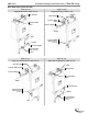
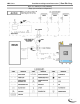
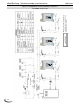
CHS boilers are supplied with an automatic air removal device to aid in the purging of air
from the boiler during the initial fill. Place this devise in the location indicated in Figures
10-1 through 10-3.
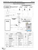
Expansion Tank – The expansion tank must be sized in accordance with the water volume of the system as well
as the firing rate of the appliance. It is important to locate the expansion tank, and make-up water fill, on the
inlet side of any circulator in the system, as doing so will guarantee the lowest pressure in the system will be at
least equal to the tank and make-up water pressure. See examples in Figures 10-5 and 10-6.
Ensure the expansion tank cannot become isolated from the boiler anytime the system is
operating. Failure to follow these instructions may result in discharge of the Pressure
Relief Valve may result in property damage or personal injury.
The installation of flow checks, motorized valves or other shutoff devices (other than for
the purpose of servicing) are not permitted between the location of the "Closely Spaced
Tees" and the expansion tank; see Figures 10-5 and 10-6.