
Manual

CHS Series Installation and Operation Instructions │ Slant Fin Corp.
67
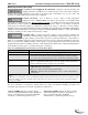
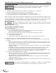
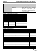
Table 15-1 Troubleshooting Chart
PROBLEM
POSSIBLE CAUSE
CORRECTIVE ACTION
Faulty sensor
Check resistance of sensor and compare to
thermistor resistance chart, see Table 15-2. (Note
the Outlet sensor incorporates two sensors, check
resistance individually.)
Hold 110 – Ignition failure
occurred (failure to prove
flame after 3 ignition
attempts)
Spark cable disconnected
Ensure that the high voltage spark cable is
securely connected to the spark generator and the
igniter electrode. Check that the green ground
wire is securely attached to the ¼” quick connect
tab on the igniter electrode.
Blocked venting
Check for blockage of the exhaust-vent, Air-inlet,
combustion blower, gas valve venturi, heat
exchanger etc.
Insufficient gas line pressure
Ensure the manual gas shutoff valve is open.
Refer to Section 9.0 GAS VALVE AND
BURNER SETUP.
Flame rod disconnected
Verify that the flame rod signal wire is securely
attached to the flame rod and the Sola controller.
No 120VAC to Spark Generator
Check wiring from Sola controller to spark
generator. With an AC voltmeter measure voltage
across J5-6 and ground (the Sola controller
chassis is connected to the 120VAC supply
ground) during trial for ignition.
Faulty Spark Generator
During trial for ignition check for arc on spark
electrode via the observation port located next to
the spark electrode in the burner door. If the spark
generator is receiving 120VAC and no spark is
observed, replace the spark generator.
No 24VAC to Gas Valve
Check the wiring harness for loose or interrupted
connections of the gas valve wiring. With an AC
voltmeter, measure the voltage between Sola
controller terminals J5-2 to J4-10. There should be
24VAC present during trial for ignition, if not
replace Sola controller.
Faulty Gas Valve
The gas valve emits an audible click when it
switches on or off. If the Sola controller is
providing 24VAC to the gas valve, and the wiring
is intact, it should be possible to detect if the valve
is responding.
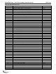
Lockout 113 – Flame circuit
timeout
A flame circuit shorted to ground
may show up as a flame circuit
timeout. High resistance shorts can
display as Lockout 113.
Check to ensure condensate drain is not blocked.
Check to ensure no voltage is applied to R & CH
terminals. If using 4-20mA input, check to ensure
current is not greater than 21mA.
Lockout 122 – Lightoff rate
proving failed
Blower is not turning on
See “Blower not operating” below.
Missing or incorrect blower
feedback signal
See Hold 62 above.
Blower is always on
See “Blower operating at high speed while burner
is off” below.
Alert 128 - Modulation rate
was limited due to IAS open
Incorrect Sola controller.
Replace control with correct model.
Lockout 138 – Flame too low
Blocked venting
Check for blockage of the exhaust-vent, Air-inlet,
combustion blower, gas valve venturi, heat
exchanger etc.