This manual must be left with owner and should be hung on or adjacent to the boilerfor reference. ® C US COMMON VENTING MODELS CHS-300 through CHS-399 INSTALLATION AND OPERATING INSTRUCTIONS TABLE OF CONTENTS 1.0 2.0 3.0 4.0 5.0 6.0 INTRODUCTION ............................................. 2 SPECIFICATIONS .............................................3 BOILER LOCATION .........................................7 CHS 300-399 COMMON VENTING ASSEMBLY INSTRUCTIONS ...........................
CHS Series CHS 300-399 Common Venting │Slant Fin Corp. 1.0 INTRODUCTION This manual is to be used in addition to the Installation and Operation Instructions provided with the Slant/Fin CHS Boilers (CHS – 40). General Installation Requirements The installation of the CHS 300-399 Common Venting system, piping and termination must conform to the requirements of this manual, the Installation and Operation Instructions for the Slant/Fin CHS Boiler, your local authority and the National Fuel Gas Code ANSI Z223.
CHS 300-399 Common Venting │Slant Fin Corp. CHS Series 2.0 SPECIFICATIONS Common Vent Manifold Configurations The CHS 300-399 Common Venting is available in 2 configurations; each configuration is applicable to a certain boiler combination. The manifolds can be assembled to direct Exhaust Gas and Combustion Air-Inlet piping to the left or right. Table 2-1 CHS 300-399 Common Venting PART NO.
CHS 300-399 Common Venting │Slant Fin Corp. CHS Series Table 2-2 Parts Included w/ CHS 300-399 Common Venting DESCRIPTION Qty per CHS 300-399 Air-Inlet Appliance (9” short) 1 / system Adapter 4” 9.0” (short) 1 / system Exhaust Appliance 9.96” (medium) 1 / system Adapter 4” 2 1 10.93” (long) 1 / system 1 Siphon PART No.
CHS 300-399 Common Venting │Slant Fin Corp. CHS Series Table 2-3 Acceptable CHS Common Vent and Termination Parts 1 DESCRIPTION PART No. COMMENTS Elbow 6” 2 Straight Pipe Length 6” 3 818 205 (45° Elbow) 818 206 (87 ° Elbow) - 818 194 (6” x 12”) 818 195 (6” x 24”) 818 196 (6” x 36”) 818 197 (6” x 72”) - Connector Ring 6” 4 818 198 Mandatory at every connection. Support Clamps 6” 5 818 199 Mandatory every 75” spaced on vertical runs and every 40” on horizontal runs.
CHS Series CHS 300-399 Common Venting │Slant Fin Corp. Exhaust Vent & Combustion Air-Inlet Piping The Slant/Fin CHS 300-399 are certified as a “Category IV” boiler requiring a “Special Venting System,” designed for pressurized venting. The Exhaust and Combustion Air-Inlet must be DIRECT VENTED to the outdoors, using the venting materials outlined in Table 2-3 of this manual. Under no conditions shall the products of combustion be vented into a masonry chimney.
CHS 300-399 Common Venting │Slant Fin Corp. CHS Series 3.0 BOILER LOCATION Boiler Mounting There are two methods of mounting Slant/Fin CHS 300-399 boilers. One option is to mount the boilers directly to the wall using the wall mounting brackets provided with the boilers. The other method is to use CHS’s Floor Stand (P/N 818 169) and Floor Stand Twinning Kit (P/N 818 220). Mounting the boilers requires a minimum of two people to lift the boilers into place.
CHS 300-399 Common Venting │Slant Fin Corp. CHS Series Floor Stand Mounting Method CHS’s Floor Stands and Twinning Kits are designed with precise height and spacing for assembling the Common Vent Manifold System. One Twinning Kit is required to joint two Floor Stands together; two Twinning Kits are required to join three Floor Stands together. P/N 818 169 – CHS 300-399 Floor Stand P/N 818 220 – Floor Stand Twinning Kit 1.
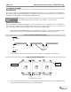
CHS 300-399 Common Venting │Slant Fin Corp. CHS Series 4.0 COMMON VENT MANIFOLD SYSTEM ASSEMBLY INSTRUCTIONS Before commencing the assembly of the CHS 300-399 Common Venting, identify which direction to direct the Exhaust Gas and Combustion Air-Inlet piping. The direction will dictate the length the branches need to be cut to.
CHS 300-399 Common Venting │Slant Fin Corp. CHS Series Lubricate During Assembly When assembling the Exhaust and Air-Inlet piping, apply Centrocerin (a water based lubricant) to each gasket and male end, to ease the assembly process, and to prevent gasket damage. Failure to apply Centrocerin lubricant to each connection may cause the gasket to be damaged or dislodged during assembly, resulting in property damage, personal injury or death.
CHS 300-399 Common Venting │Slant Fin Corp. CHS Series Air-Inlet Manifold Assembly Instructions (Steps 1-6) (Model CHS 300-399 Shown) Apply Centrocerin lubricant to each gasket and male end 1 Air-Inlet Support 1. Air-Inlet Supports – Remove the front door of the boiler. Using two 1/4" x 3/4" Drill Point Screws, fasten the Air-Inlet Support to the front right corner of the boiler cabinet as illustrated. Repeat for each boiler. 1/4” x 3/4" Drill Point Screws Air-Inlet Support 2 2.
CHS 300-399 Common Venting │Slant Fin Corp. CHS Series 4. Branch – Insert the 6” x 4” Branch fittings into the 4” Elbows installed in Step 3, starting with the boiler on the left (start with the boiler on the right if the Combustion Air-inlet is being piped to the left). Use Centrocerin lubricant and a Connector Ring at each connection.
CHS 300-399 Common Venting │Slant Fin Corp. CHS Series Exhaust Manifold Assembly Instructions (Steps 7 to 13) (Model CHS 300-399 Shown) Exhaust Support Top of Air-inlet Support 7 7. Exhaust Support – Fasten the Exhaust Supports to the top of the Air-inlet Supports using two ¼” x 1” Machined Screws; sandwich the top of the Air-inlet Support in between the two, as illustrated, to secure the Air-inlet Manifold in place.
CHS 300-399 Common Venting │Slant Fin Corp. CHS Series 4” Connector Ring Elbow 10. Branch – Insert the 6” x 4” Branch fittings into the 4” Elbows installed in Step 9, starting with the boiler on the left (start with the boiler on the right if the Exhaust Gas is being piped to the left). Use Centrocerin lubricant and a Connector Ring at each connection.
CHS 300-399 Common Venting │Slant Fin Corp. CHS Series 13 Connect field supplied condensate hose and route to an appropriate drain 13. Siphon – Install the Siphon to the fitting of the Horizontal Drain. Connect a field supplied condensate hose and route to an appropriate drain. Condensate Drain Check with your municipality, or local gas company, to determine if the disposal of combustion condensate is permitted in your area (e.g.
CHS 300-399 Common Venting │Slant Fin Corp. CHS Series 5.0 TERMINATION OPTIONS - DIRECT VENT The CHS 300-399 Common Venting is approved for DIRECT VENT ONLY. Installers are responsible for supplying the required Exhaust Gas and Combustion Air-inlet piping, termination components, Connector Rings and Support Clamps. Table 2.3 lists the Centrotherm – InnoFlue PPs-UV parts that are approved for terminating the Common Vent System. Terminations are to be DIRECT VENT ONLY.
CHS 300-399 Common Venting │Slant Fin Corp. CHS Series Figure 5-2 Roof Termination Details Bird Screen PPs-UV Exhaust Vertical Min. 18” Air-Inlet Horizontal 4-12” or greater than 36” Min. 12” above grade and snow level Flashing Refer to Centrotherm – InnoFlue documentation included with termination components for complete installation instructions.
CHS 300-399 Common Venting │Slant Fin Corp.
CHS 300-399 Common Venting │Slant Fin Corp. CHS Series Figure 5-4 Sidewall Termination Details – Option 1 Horizontal 4-12” or greater than 36” Exhaust OUT Air-Inlet IN Exhaust Vertical Min. 18” Gas Vent Directly Below Keep Free of Obstructions Air-Inlet Min. 12” above ground and snow level Bird Screen PPs-UV Refer to Centrotherm – InnoFlue documentation included with termination components for complete installation instructions.
CHS 300-399 Common Venting │Slant Fin Corp. CHS Series Figure 5-5 Sidewall Termination Details – Option 2 Horizontal 4-12” or greater than 36” Exhaust OUT Air-Inlet IN Exhaust Vertical Min. 18” Gas Vent Directly Below Keep Free of Obstructions Air-Inlet Min. 12” above ground and snow level Bird Screen PPs-UV Refer to Centrotherm – InnoFlue documentation included with termination components for complete installation instructions.
CHS Series CHS 300-399 Common Venting │Slant Fin Corp. 6.0 CHECKLIST Installation Checklist 1. Read and understand this manual and the Installation and Operation Instructions provided with the Slant/Fin CHS 300-399 Boilers (CHS – 40). Understand the dangers associated with improper installation of the boilers, CHS 300-399 Common Venting, vent and termination. 2. Preform the Installation Checklist from the boiler Installation and Operation Instructions. 3.
CHS Series CHS 300-399 Common Venting │Slant Fin Corp. Annual Inspection Checklist The Slant/Fin CHS 300-399 Common Venting must be inspected at the beginning of every heating season by a Qualified Technician. 1. For each boiler perform the Annual Inspection Checklist in the boiler Installation and Operation Instructions. 2. Inspect the CHS 300-399 Common Venting termination components for damages caused by exposure to weather elements.
CHS Series CHS 300-399 Common Venting │Slant Fin Corp.
U.S.A. Slant/Fin Corporation • 100 Forest Drive Greenvale, NY 11548 • 516-484-2600 www.slantfin.com ©Slant/Fin Corp.