EUTECTIC EC-10 OIL-FIRED WATER BOILERS/NO. 2 OIL ASSEMBLY INSTRUCTIONS Tools required: • • • • 1 Phillips screwdriver 1 Wide flat screwdriver 1 13mm open end wrench 1 19mm open end wrench ©Slant/Fin Corp. 2014 • Printed in the U.S.A. 1214 • Part # 470901000 • Publication No. EC-10-50 Rev.
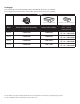
Packaging: The following table shows the package numbers included with the boiler to be installed. The packages are presented in the order in which they should be opened for assembly.
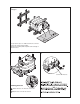
1 Packagees Put a protective piece of cardboard on the floor in front of the boiler casting sub-assembly. Take the body off the pallet and put it down vertically on the burner door. 2 3 2 3 3/8” Bolt, Nut & Washers 1 Installing the base Attach the base onto the front of the boiler. Clip the base onto the rear section.
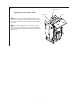
Reverse the direction of opening of the burner door if necessary (opening at left). When the burner leaves the factory, the burner door opens towards the right. Perform operations 4.1, 4.2 and 4.3 below to open the burner door towards the left (if absolutely necessary). 4.2 3 2 4.1 4 1 3 13 5 1 2 8575N019 - Remove the cast iron hinge pin fixed by the 2 screws on the right-hand side 8575N018 for the burner door . Put the two screws back Loosen the 2 top and bottom nuts.
Installing the insulating material notch in front 2 1 8575N021A - Pass the strap between the cast iron body and the base. - Install the insulation around the body, folding the bottom on each side of the boiler inside the base.
7 6 EC-13 1 4 5 6 3 2 EC-14 EC-15 85 75 N 3 02 B 4 EC-16 1 Installing the control panel support cross bar - Put the support cross bar into place on the boiler body, positioning it on : • the M8 studs at the front, • the assembly rod 8 - Fix it at the front with 2 HM8 flanged nuts - Fix the 3rd section with : • 1 HM8 x 30 screw and the 3rd section positioning pin • 1 flanged nut + flanged nuts . , on the assembly rod.
9 Honeywell Aquastat Putting the burner cable in place Cable clamp. Attach one end of the burner wiring harness (cable) to control box, and route other end through hole in control panel support cross bar. (Shown with Honeywell aquastat control.) Attach cable clamp (from bag of screw) to cable to limit travel of cable through hole in control panel support cross bar. (Cable clamp will need adjustment when installing burner.
10 Installing the side panels 5 4 3 3 1 1 1 2 8575N025B Put the front of the side panel into place, engaging the lower notch of the panel in the cross bar of the base. Make sure that the lower fold in the panel is correctly positioned under the fold of the cross bar. Straighten the side panel and pull it upwards. Attach the side panel to the lugs of the control panel support, pulling its upper fold upwards such that the upper fold of the side panel is centred and blocked between the two notches.
11 12 2 1 1 1 2 2 2 85 8575N031D 75 N4 49 A Installing the cover Installing the rear panel Hang up the rear panel on the side panels. Put the cover into place and push it forwards to fix it in the two side panel bushings. Fix it using four self tapping screws + serrated washers delivered in the fasteners pack. Fix it at the back with 2 ø 3.94 x 12.7 screws + 2 ø 4 serrated washers.
14 Assembling the burner Fix the gasket with the flange on the burner door using four 3/8”–16 studs, supplied. (screw shorter length of metric thread into burner door.) 1 85 75 N2 39 B Push the burner into the burner door until it will not go any further. Fix the burner using four washers and hex nuts, supplied. Cable clamp. If hinged door is changed to left side, cable routing must be moved to the right.
15 1 4 Assembling the front cap 3 4 Lift the window. 3 Attach the front cap in the openings near the bottom of the side panels. Slide the two lugs of the front cap into the notches of the side panels and then fix it in the two spring clips. 2 Push the front cap into contact with the side panels and fix it using the two black RLS M 6 x 10 screws (S/F part no. 470128000) (delivered in the casing screw bag).
17 Stick the nameplate and other labels on the side of the boiler. Rating plate. Place “DANGER” label as shown, near front. 1 Place nozzle spec/burner set up procedure, near front as shown. 4 Place “Installing Boiler Label” near rear as shown. 5 Place “ETL” label where shown. 2 3 4 5 ©Slant/Fin Corp. 2014 • Printed in the U.S.A. 614 • Part # 470901000 • Publication No. EC-10-50 Rev.B SLANT/FIN CORPORATION., Greenvale, N.Y. 11548 • www.slantfin.