S1689 ULi M1689 Micro-ATX Motherboard User’s Guide 1
Declaration of Conformity According to 47 CFR, Parts 2 and 15 of the FCC Rules The following designated product: EQUIPMENT: MAINBOARD is a Class B digital device that complies with 47 CFR Parts 2 and 15 of the FCC Rules. Operation is subject to the following two conditions: 1. This device may not cause harmful interference. 2. This device must accept any interference received, including interference that may cause undesired operation.
Federal Communications Commission Statement This device complies with FCC Rules Part 15. Operation is subject to the following two conditions: * This device may not cause harmful interference. * This device must accept any interference received, including interference that may cause undesired operation. This equipment has been tested and found to comply with the limits for a Class B digital device, pursuant to Part 15 of the FCC Rules.
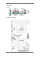
TABLE OF CONTENTS Chapter 1 Introduction............................................................1 1-1 Product Specifications ..................................................................................1 1-2 Package Contents .........................................................................................2 1-3 Back Panel ...................................................................................................3 1-4 Motherboard Layout................................................
Revision History Revision Description P/N V.
Chapter 1 Chapter 1 Introduction 1-1 Product Specifications CPU - Supports AMD Socket-939 Althon 64 / Sempron CPU - Processor interface via 2000MT/s HyperTransport bus Chipset - ULi M1689 Memory - Four 184- pin DDR DIMMs up to 4GB - Supports Dual Channel DDR266/333/400 memory Due to CPU specifications limitation, two DDR400 memory modules inserted into DIMM1/3, three DDR400 into DIMM1/2/3, or four DDR400 into DIMM1/2/3/4 is not recommended.
Chapter 1 Fast Ethernet - Supports 10/100Mb Fast Ethernet with external Realtek PHY Boot-Block Flash ROM - Award system BIOS supports PnP, APM, DMI, ACPI, & Multi-device Booting features Rear Panel I/O ports - PS/2 Mouse and Keyboard port - Four USB ports and one RJ45 connector - Two 9-pin D-Sub male Serial ports - 25-pin D-Sub female Parallel port - Audio I/O jacks (Line-in, Line-out and Mic-in) Internal I/O connectors - Two 3x1 pin fan connectors - Two 5x2 pin USB connectors for additional
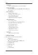
Chapter 1 1-3 Back Panel S1689 PS/2 Mouse Printer Port RJ-45 port Line-In port Line-Out port Microphone port PS/2 Keyboard Serial ports USB 2.
Chapter 2 Chapter 2 Hardware Setup 2-1 PC D.I.Y. Assembly Instructions 1. Jumper Setting: Set the CPU External Clock, Frequency Ratio and the CPU voltage according to the instruction printed on the manual or silkscreen printed on the mainboard. 2. Installing FDD and IDE devices: Aligned the red colored edge of the cable with the pin 1 of the drive connector on the mainboard and gently attached it. Attach the other end of the cable by aligning the colored edge to the pin 1 of the device connector.
Chapter 2 5. Mounting a Mainboard into a Chassis: Use standoffs and screws to securely mount the mainboard and make sure that all the mounting holes are properly screwed. 6. Adding an expansion card: Gently fasten the card to the proper slot. 7. Connecting I/O ports and device connectors: Simply plug the cable into the respective device port or connector as shown in the manual or silkscreen printed on the mainboard. 8.
Chapter 2 2-2 自行組裝電腦之作業指導重點 (Chinese) 1. 主機板硬體組態設定: 依據使用手冊上面的指令或印刷在主機板上的文字來設定 CPU 外頻,倍頻及電 壓或其它設定。 2. 安裝 FDD 和 IDE 裝置: 將排線較長一端的排線插入主機板 IDE 插槽並且紅色線對準插槽的第一針腳 (Pin 1),檢視排線接頭是否完全插入插槽,同時排線較短的一端也依序插入軟碟 機,硬碟機等儲存裝置。 3. 安裝 CPU: 將 CPU 的缺角對準 CPU 腳座的缺角並小心地將 CPU 插在腳座上,按下旁邊的 固定桿以固定 CPU。 4.
Chapter 2 5. 主機板固定: 用銅柱及螺絲將主機板安裝在機殼底座並確定每個孔洞均已被鎖上,尤其注意主 機板底下不可有多餘的銅柱以避免造成短路。 6. 增加介面卡: 將介面卡(例 : 網路卡,音效卡等)插在適當的介面卡擴充插槽,並將卡上的鐵片 鎖緊在機殼上。 7. 連接 I/O 埠和其他設備的接頭: 適當地將排線插入各設備的插槽,記得必須將排線與插座的第一針腳互相對準, 請參照使用者手冊的主機板平面圖。 8.
Chapter 2 2-3 Français Instructions de montage du PC D.I.Y (French) 1. Positionnement des cavaliers (jumpers) Positionnez les cavaliers de la fréquence d’horloge externe du microprocesseur, du rapport de fréquence et de la tension d’alimentation du microprocesseur, suivant les instructions qui figurent dans le manuel ou qui sont sérigraphiées sur la carte mère. 2.
Chapter 2 5. Montage d’une carte mère dans son châssis A l’aide des jauges d’espacement et des vis fournies, fixez fermement la carte mère dans son emplacement, et vérifiez que tous les trous destinés à la fixation sont utilisés et les vis sont correctement serrées. 6. Ajout d’une carte d’extension Fixez avec précaution la carte dans le logement adapté. 7.
Chapter 2 2-4 Deutsch PC D.I.Y.-Montageanleitung (German) 1. Steckbrücken Konfigureren Die Anweisungen zum Einstellen des externen Prozessortakts, der Taktfrequenz und der Prozesorspannung finden Sie im Hand buch oder direct auf dem Motherboard. 2. Disketten- und Festplattenlaufwerke Installieren Schließen Sie die rot markierte Kabelseite an Stift 1 des Laufweksanschlußes auf dem Motherboard an. Bringen Sie das andere Kabelende am GeräteanSchluß.
Chapter 2 5. Motherboard im Gehäuse montieren Verwenden Sie das modul nach Schraubenund Abstandhalter, um das Motherboard stabil im Gehäuse zu montieren. Achten Sie darauf, daß sämtliche Montagöffnungen korrekt miet einer Schraube versekhen werden. 6. Steckkarte einbauen Führen Sie die Karte vorsichtig in einen geeingneten Steckplatz ein. 7. Vo- und Geräteanschluße verbinden Verbinden Sie das Kabel mit dem ensprechenden Geräteanschluß.
Chapter 2 2-5 Самостоятельная сборка ПК (Russian) 1. Установка перемычек Установите параметры Вашего таймера ЦПУ, значение частоты и напряжение ЦПУ согласно инструкциям, приведенным в руководстве, или надписям на системной плате. 2. Установка Накопителя на гибких дисках и IDE устройств Совместите кромку красного цвета кабеля и PIN1 разъема накопителя на системной плате, затем аккуратно соедините их. Присоедините другой конец кабеля к разъему накопителя, совместив кромку красного цвета с PIN1 накопителя.
Chapter 2 5. Монтаж системной платы на шасси Для надежного монтажа системной платы используйте крепления и винты. Убедитесь, что все монтажные отверстия закреплены винтами. 6. Установка карт расширения Аккуратно установите карту в соответствующий слот 7. Подсоединение портов ввода/вывода и разъемов устройств Подсоедините кабель к соотве5тствующему порту или разъему согласно инструкциям, приведенным в руководстве или напечатанным на системной плате. 8.
Chapter 2 2-6 PC D. I. Y. 조립 설명 (Korean) 1.점퍼설정 매뉴얼이나 메인보드에 나와있는 설정방법을 참고하여 CPU 의 외부클럭, 주파수, 전압 등을 설정합니다. 2. 메인보드 장착 드라이버를 이용하여 케이스에 정확하게 메인보드를 장착합니다. 3. CPU 장착 CPU 의 모서리를 보면 표시가 되어있습니다. 이 부분이 1 번 핀입니다. 이 부분을 메인보드의 CPU 소켓에 맞추어 CPU 를 장착합니다. 4. 메모리 장착 메모리의 금색부분이 보이지 않을 때까지 메모리 슬롯에 메모리를 꼽습니다. 완벽하게 꽂히면 슬롯 옆에 있는 고정핀이 자동으로 올라옵니다.
Chapter 2 5. 플로피 디스크, 하드디스크 케이블 연결 케이블의 1 번선은 빨간색입니다. 이 선을 기준으로 하여 메인보드의 1 번핀에 정확하게 장착합니다. 커넥터가 확실하게 연결될 수 있도록 하십시오. 6. 외부 카드의 장착 비디오카드 및 다른 외부 장착용 카드를 장착합니다. 7. I/O 포트, 기타장치 연결 매뉴얼이나 메인보드에 나와있는 설정방법을 참고하여 I/O 장치와 기타장치를 연결합니다. 8. 파워 써플라이 케이블 연결 ATX 파워케이블을 메인보드에 연결합니다. 감사합니다.
Chapter 2 2-7 Connector and Jumper Settings Connectors are used to link the system board with other parts of the system, including power supply, keyboard, and the various controllers on the front panel of the system case. The power supply connector is the last connection to be made while installing a motherboard. Before connecting the power supply, please make sure it is not connected to the power source. All cables that provided by CHAINTECH come with a security-proof.
Chapter 2 After being disconnected for a certain period of time, the poly-fuse will return to its normal state and the keyboard or USB connector can function properly again. Unlike conventional fuses, the poly-fuse will not need to be replaced, relieving users from such inconveniences. CN11 (Front Panel Connector): PWR-SW (Over-ride Power Button Connector): The power button on the ATX chassis can be used as a normal power switch as well as a device to activate the Advanced Power Management Suspend mode.
Chapter 2 5. HD-LED (IDE - Activity LED Connector): The IDE- activity LED lights up whenever the system reads/writes to the IDE devices. FDD1 (Floppy Connector): The motherboard provides a standard floppy disk drive connector that supports 360K, 720K, 1.2M, 1.44M and 2.88M floppy disk types. It is connected to a floppy disk drive of 34 pins.
Chapter 2 JP3/4 (Power On by USB 0/1/2/3, 4/5/6/7): JP3 -> USB 0/1/2/3, JP4 -> USB 4/5/6/7 An USB keyboard hot key or an USB mouse-click can activate this board. To use this function, select a hot key of your choice at the USB Resume from S3 option under Wake Up Events in the BIOS's Power On Management screen.
Chapter 3 Chapter 3 BIOS Setup Program Phoenix-Award BIOS ROM has a built-in setup program that allows users to modify the basic system configuration. This information is stored in CMOS RAM so that it can retain the setup information even when the power is turned off. Press [Delete] when you Power on or Reboot the computer system..The primary screen as shown in Figure 3-1 is a list of the menus and functions available in the setup program.
Chapter 3 3-3 Advanced Chipset Features In this section a list of advanced chipset functions are provided to users. By choosing the [Advanced Chipset Features] option from the CMOS Setup Utility menu (Figure 3-1), the screen below is displayed. This sample screen contains the manufacturer's default values for the motherboard. 3-4 Integrated Peripherals This section provides information on setting up the peripheral devices.
Chapter 3 3-11 Save and Exit Setup If you select this and type [Y] followed by [Enter], the values entered in the setup utilities will be recorded in the CMOS memory of the BIOS chip. 3-12 Exit Without Saving Selecting this option and pressing [Y] followed by [Enter] lets you exit the Setup program without recording any new values or changing old ones.
Chapter 4 Chapter 4 Software Insert the support CD that comes with your motherboard into your CD-ROM driver or double-click the CD drive icon in [My computer] to enter the setup screen. 4-1 Driver Setup We begin with the installation of drivers. To do so, simply follow the instructions below. Step-by-step guide 1. Make certain that your computer and display are powered on. 2. Insert the support CD into the CD-ROM and the autorun screen will automatically pop up, as shown in the following image.
Chapter 4 Integrated Driver Five drivers are integrated into the item. They are ULi PCI 10-100 Fast Ethernet Controller Driver, ULi USB 2.0 Controller Driver, ULi PCI to AGP Controller Driver, ULi M5289 SATA Controller Driver, ULi M5289 SATA Raid Function. To install them, simply follow the instructions below Step-by-step guide 1. Click Integrated Driver, then the Welcome screen will show up. 2. After reading the contents, click Next> to proceed with the Setup program. 3.
Chapter 4 4. Ignore the message below and click Continue Anyway. 5. The following message simply tells you that it is better to install the driver prior to the potential installation of the graphics driver. 6. Choose Yes, I want to restart my computer now and click OK to restart the computer.
Chapter 4 DirectX 9.0c Allows you to install the latest DirectX 9.0c Driver. To do so, please follow the instructions below. Step-by-step guide 1. Click DirectX 9.0c to enter the Installing Microsoft DirectX. After reading the license agreement, choose I accept the agreement then click Next>. 2. Click Next> to proceed with the installation.
Chapter 4 3. Click Finish to complete the installation. Realtek Codec Audio Driver To install this, simply follow the instructions below. Step-by-step guide 1. Click Realtek Codec Audio Driver and wait until the figure below pops up. 2. Select Yes, I want to restart my computer now then click Finish to complete the process.
Appendix Appendix How to Install Windows 2000/XP On a SATA Drive a) Copy the SATA drivers from the driver CD. (CDROM: \Raid\Integrated Driver\sata 50xx\Driver Disk\Raid;Txtsetnr.oem)into a floppy disk b) When the message “Press F6 if you need to install a third party SCSI or RAID driver” shows up during Win2000/XP installation, press “F6” c) Put the floppy disk in and wait for a little while. d) Press “S” to install other drivers when next screen pops up.
Note NOTE All rights are reserved for the products and corporate names/logos that appear in this manual to their original owners. We reserve all rights to change this manual .All information is subject to change without notice.
How to Contact CHAINTECH How To Contact CHAINTECH Please do not hesitate to contact us if you have any problem about our products. Any opinion will be appreciated. For Asia, Africa, Australia and Pacific Island: CHAINTECH COMPUTER CO., LTD 4F.-5, No.16, Jian 8th Rd., Zhonghe City, Taipei County 235, Taiwan Tel: +886-2-8226-8188 Fax: +886-2-8226-8199 URL: http://www.chaintech.com.tw E-mail: sales@chaintech.com.