
Installation Sheet


4
C
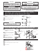
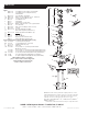
Align Flushometer Body and securely tighten first the Tailpiece
Coupling (1), then the Vacuum Breaker Coupling (2), and finally the
Spud Coupling (3). Use a wrench to tighten these couplings in the
order shown.
B
Align Flushometer directly above the Vacuum Breaker Flush
Connection by sliding the Flushometer Body IN or OUT as needed.
Tighten Vacuum Breaker Coupling by hand.
A
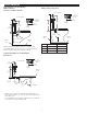
Lubricate tailpiece O-ring with water. Insert Adjustable Tailpiece
into Control Stop. Tighten Tailpiece Coupling by hand.
Maximum adjustment of the Sloan Adjustable Tailpiece is 1/2” (13
mm) IN or OUT from the standard 4-3/4” (121 mm) (centerline of
Flushometer to centerline of Control Stop).
If roughing-in measurement exceeds 5-1/4” (133 mm), consult factory
for longer tailpiece.
NOTE
A
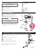
Remove Control Stop Cap.
C
Remove Outside and Inside Covers and old Inside Parts Kit.
B
Turn off water supply at Control Stop. Push Valve Handle to relieve
water pressure.
A
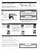
Slide Spud Coupling, Nylon Slip Gasket, Rubber Gasket and Spud
Flange over Vacuum Breaker Tube.
B
Insert Tube into Fixture Spud.
C
Hand tighten Spud Coupling onto Fixture Spud.
G-44
FRICTION
RING
C/L
SUPPLY
ADJUSTABLE
TAILPIECE
C/L
FIXTURE
CONTROL STOP
O-RING
TAILPIECE COUPLING
VACUUM
BREAKER FLUSH
CONNECTION
VACUUM
BREAKER
COUPLING
FLUSHOMETER
BODY
4-3/4”
(121 mm)
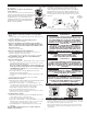
D
Remove old Handle Assembly and Gasket.
Install Chrome Handle Cap with Gasket to handle opening on
Flushometer Body. Tighten Chrome Handle Cap securely.
E
NOTE: An extra H-553 Tail O-ring is included in the event leakage occurs
if the valve is repositioned during the installation of the new Sloan ECOS
®
Electronic. Use only as needed.
H-553
TAIL O-RING
A
C
E
B
D
RESS SERIES
INSTALLATIONS ONLY
SPUD
COUPLING
If cutting Vacuum Breaker Tube to size, note that Critical Line (C/L) on
Vacuum Breaker must typically be 6”
(152 mm) above fixture. Consult Code for details.
NOTE
VACUUM
BREAKER
REPAIR KIT
VACUUM
BREAKER
TUBE
SPUD COUPLING
NYLON SLIP
GASKET
RUBBER GASKET
SPUD FLANGE
4 - INSTALL VACUUM BREAKER FLUSH CONNECTION
5 - INSTALL FLUSHOMETER
6 - WHEN RETROFITTING AN EXISTING VALVE, START HERE. REMOVE COMPONENTS
FROM EXISTING FLUSHOMETER (RESS RETROFIT INSTALLATIONS ONLY)
1
2
3