
Installation Sheet


55
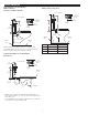
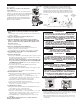
O-RING
REGULATOR
(MUST BE
INSTALLED
PAST O-RING)
FLEX TUBE
DIAPHRAGM
Fixture Regulator Color
& Flush
1.28 gpf (4.8 Lpf) Closet Green
0.5 gpf (1.9 Lpf) Urinal Green
Reference Chart
Fixture & Flush
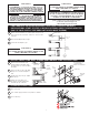
0.13 gpf (0.5 Lpf)Cartridge Assembly
0.25 gpf (0.9 Lpf) Cartridge Assembly
Reference Chart
The Dual-Flush Volume of the Sloan ECOS
®
Electronic is controlled by the Flex
Tube Diaphragm Kit. Regulators are identified by color.
RESS-C Sloan ECOS
®
Electronic valves are supplied with it’s lowest flush volume configuration.
When installing a new Regulator on a Flex Tube Diaphragm Kit, be sure to push the Regulator past the O-ring when
installing.
Note: Never use more water than needed. Low Consumption water closets will not function properly on excess water.
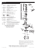
SLOAN ECOS
®
ELECTRONIC ASSEMBLY
B
Insert metal end into hole in base of Sloan
ECOS
®
Electronic Assembly. O-ring must be
fully inserted into the hole.
A
Make sure Flush Volume Regulator is
Installed Past O-ring.
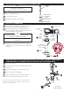
O-RING
VALVE
BODY
FLEX TUBE
DIAPHRAGM
C
Push Diaphragm securely against underside of Sloan ECOS
®
Electronic Assembly. Place entire Assembly onto the Valve Body.
To facilitate installation, the O-ring on the diaphragm assembly must be wet for easier insertion. NOTE: Sensor Lens must face directly forward. Rotating the
Sensor to either side will decrease the Sensor’s ability to detect a target.
7 - SLOAN ECOS
®
ELECTRONIC DUAL-FLUSH VOLUMES (RESS RETROFIT
INSTALLATIONS ONLY)
8 - ASSEMBLE FLEX TUBE DIAPHRAGM TO SLOAN ECOS
®
DUAL-FLUSH ELECTRONIC
ASSEMBLY
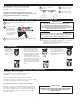
A
Thread Locking Ring
onto Valve Body.
B
Use Strap Wrench
provided to tightly secure
Locking Ring.
If retrofitting the Optima Plus onto a Zurn valve body, a special Locking
Ring must be used (identified by a machined groove around the ring).
Order the Optima Plus with the “Z” variation to receive the unit supplied
with this Ring.
A
Remove all removable objects
in sensor view area and remove
the Tab located over the Override
Button to activate the Sensor
Module. The sensor module will
perform the start-up routine for
one minute with LED blinking.
B
After the start-up routine is
complete, for the first ten (10)
minutes of operation, a Visible
Red Light flashes in the Sensing
Window of the Optima Plus
Flushometer when a user is
detected.
9 - TIGHTEN LOCKING RING
10 - REMOVE TAB TO ACTIVATE SENSOR MODULE
The Locking Ring must be installed down past the valve body
threads by at least one thread. If difficulty is experienced
installing the Locking Ring, turn the Locking Ring back and
forth, each time working it further down the threads. The
Locking Ring will act as a thread chaser in the event there has
been a build-up of matter on the threads of the old valve body.
!!! IMPORTANT !!!
The self adaptive sensor automatically adapts to the surrounding
enviroment when the tab on the override button is removed.
No manual adjustments are required. Start-up mode will take
approximately one (1) minute to complete its cycle and it is important
that no non-permanent target is present at this time. If the target is
permanent, the sensor will adapt itself around this target. A 3 seconds
long Red light on and followed with slow Red light blinking in sensor
window indicates sensor is in the start-up mode. When the start-
up cycle is complete, one red light blink indicates lithium batteries
are installed and two red light blinks indicates alkaline batteries are
installed.
NOTE