
Installation Sheet


7
LAWS AND REGULATIONS PROHIBIT THE USE OF
HIGHER FLUSHING VOLUMES THAN
LISTED ON FIXTURE OR FLUSHOMETER
!!! IMPORTANT !!!
THE CONTROL STOP SHOULD NEVER BE OPENED
TO THE POINT WHERE THE FLOW FROM THE VALVE
EXCEEDS THE FLOW CAPABILITY OF THE FIXTURE. IN
THE EVENT OF A VALVE FAILURE, THE FIXTURE MUST BE
ABLE TO ACCOMMODATE A CONTINUOUS FLOW FROM
THE VALVE.
!!! IMPORTANT !!!
WITH THE EXCEPTION OF CONTROL STOP INLET, DO
NOT USE PIPE SEALANT OR PLUMBING GREASE ON ANY
VALVE COMPONENT OR COUPLING!
!!! IMPORTANT !!!
PROTECT THE CHROME OR SPECIAL FINISH OF SLOAN
FLUSHOMETERS — DO NOT USE TOOTHED TOOLS TO
INSTALL OR SERVICE THESE VALVES. USE A SLOAN
A-50 SUPER-WRENCH™, SLOAN A-109 PLIER WRENCH
OR SMOOTH JAWED SPUD WRENCH TO SECURE ALL
COUPLINGS. ALSO SEE “CARE AND CLEANING” SECTION
!!! IMPORTANT !!!
THIS PRODUCT CONTAINS MECHANICAL AND/OR
ELECTRICAL COMPONENTS THAT ARE SUBJECT TO
NORMAL WEAR. THESE COMPONENTS SHOULD BE
CHECKED ON A REGULAR BASIS AND REPLACED AS
NEEDED TO MAINTAIN THE VALVE’S PERFORMANCE.
!!! IMPORTANT !!!
THE STRAP WRENCH PROVIDED WITH SLOAN ECOS
®
ELECTRONIC IS A CONVENIENCE TOOL AND IS NOT TO
BE USED TO REMOVE OR INSTALL THE FLUSHOMETER
COUPLINGS. USE STRAP WRENCH ONLY TO INSTALL
SLOAN ECOS
®
ELECTRONIC LOCKING RING.
!!! IMPORTANT !!!
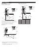
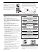
RECOMMENDED WALL PLATE LOCATIONS
CARE AND CLEANING
• Centered over Flushometer • On stall door
DO NOT use abrasive or chemical cleaners to clean flushometers as they may
dull the luster and attack the chrome or special decorative finishes. Use ONLY
soap and water, then wipe dry with clean cloth or towel.
While cleaning the bathroom tile, the Flushometer should be protected from
any splattering of cleaner. Acids and cleaning fluids can discolor or remove
chrome plating.
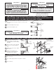
When required, replace batteries with four (4) Alkaline
AA-Size Batteries.
Note: Water does not have to be turned off to
replace Batteries.
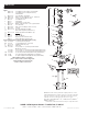
Loosen the two (2) Screws on top of unit. Remove the
complete Cover Assembly. Lift the Sensor Module from
its Plate. Unplug the Electrical Connector from Battery
Compartment Cover. Loosen the Retaining Screw
on Battery Compartment Cover and remove Battery
Compartment Cover. Install four (4) Alkaline AA-Size
Batteries exactly as illustrated.
BATTERY
COMPARTMENT
COVER
ELECTRICAL CONNECTOR RECEPTACLE
SENSOR
MODULE
RETAINING
SCREW
1. Sensor Flashes Continuously Only When User Steps Within
Range.
A. Unit in Start-Up mode; no problem. This feature is active for the first ten (10)
minutes of operation.
2. Valve Does Not Flush; Sensor Not Picking Up User.
A. Range too short; increase the range.
3. Valve Does Not Flush; Sensor Picking Up Opposite Wall or
Surface, or Only Flushes When Someone Walks By. Red Light
Flashes Continuously for First 10 Minutes Even with No One in
Front of the Sensor.
A. Range too long; shorten range.
4. Valve Does Not Flush Even After Adjustment.
A. Improper Range Adjustment; Follow Instructions and repeat steps.
B. Batteries completely used up; replace batteries.
C. Problem with Electronic Sensor Module; replace Electronic Sensor Module.
5. Red Light Blinks 4 Times When User Steps Within Range.
A. Batteries low; replace batteries.
6. Valve Does Not Shut Off.
A. Bypass orifice in diaphragm is clogged with dirt or debris, or bypass is clogged
by an invisible gelatinous film due to “over-treated” water. Remove flex tube
diaphragm and wash under running water.
Note: Size of Orifice in the Bypass is of utmost importance for
the proper metering of water by the valve. DO NOT ENLARGE
OR DAMAGE THIS ORIFICE. Replace flex tube diaphragm if cleaning
does not correct the problem.
B. Dirt or debris fouling stem or flex tube diaphragm. Remove flex tube
diaphragm and wash under running water.
C. O-ring on stem of flex tube diaphragm is damaged or worn. Replace O-ring if
necessary.
D. Problem with Electronic Sensor Module; replace Sensor Module.
7. Not Enough Water to Fixture.
A. Wrong Flush Volume Regulator installed in Flex Tube Diaphragm Kit. Install the
correct Regulator (see Section 7 of these instructions).
B. Wrong G2/ECOS model installed; i.e., 1 gpf. urinal installed on 3.5 gal.
closet fixture. Replace with proper G2/ECOS model, or refer to the G2/ECOS
Conversion Guide to convert existing unit to the proper model.
C. Enlarged Bypass in Diaphragm. Replace Flex Tube Diaphragm.
D. Control Stop not adjusted properly. Readjust Control Stop.
E. Inadequate volume or pressure at supply. Increase water pressure or supply
(flow) to valve. Consult factory for assistance.
8. Too Much Water to Fixture.
A. Wrong flush volume regulator installed in flex tube diaphragm kit. Install the
correct regulator (see Step 7 of these instructions).
B. Control Stop not adjusted properly. Readjust Control Stop.
C. Wrong G2/ECOS model installed; i.e., 3 gpf. model installed on 1.0 or 1.5 gal.
urinal fixture. Replace with proper G2/ECOS model, or refer to the G2/ECOS
Conversion Guide to convert existing unit to the proper model.
D. Dirt in diaphragm bypass. Clean under running water or replace flex tube
diaphragm.
Note: The EBV-46-A Beam Deflector is no longer required or
available for the G2/ECOS.
16 - TROUBLESHOOTING
15- BATTERY REPLACEMENT
COVER
ASSEMBLY
SENSOR
MODULE
PLATE
Install Battery Compartment Cover and secure with Retaining
Screw. Make certain that Battery Compartment Cover is fully
compressed against Gasket to provide a seal; Do Not overtighten.
Plug the Electrical Connector into the Battery Compartment Cover.
Reinstall the Sensor Module onto the Plate. Reinstall the complete
Cover Assembly onto the Plate. Tighten the two (2) Screws on top
of the unit.