
Specification Sheet


Repair Parts and Maintenance Guide
3.2.3
102008
G2 Optima Plus
®
Flushometer
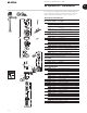
Back View
Front View
SOLENOID REPLACEMENT
Code No. Part No. Description
3325453 EBV-136-A Solenoid operator
For G2 Optima Plus
®
modules (identified by a
blue module).
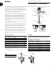
Note. Verify that rubber insert is installed
Close up
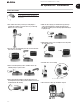
1. Turn off water and relieve pressure by loosening Tailpiece
coupling and re-tighten. Loosen and remove top screws along
with the outer cover assembly.
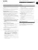
5. Make sure all O-rings (2) are installed on the grey End cap
of the new Isolated Operator. Install Isolated Operator by
threading it (clockwise) into the Housing. Tighten with fingers
beyond just snug.
2. Disconnect wire clip from battery door and remove module from
inner metal cover assembly.
6. Mount module on inner cover assembly. Reconnect the plastic
clip on the battery door.
3. Remove Solenoid by turning counter clockwise. Remove any
remaining O-rings or parts in orifice.
7. Assemble outer cover assembly.
4. Remove black plastic Housing from the threaded end of new
Isolated Operator by unscrewing (counterclockwise). It is normal
to find fluid inside this housing.
8. Turn on water at control stop. Installation complete.