
Installation Sheet
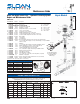

Royal and Regal Series 900™ Hydraulic Flushing System
Repair and Maintenance Guide
PARTS LIST
Item Code No. Part No. Description
1. 0301173 A-72 RB Cover
2. 0301168 A-71 Inside Cover
3. SEE THE INSIDE PARTS KIT CHART BELOW
4. 3323182 V-651-A Vacuum Breaker Repair Kit
5. 0308690 H-550 RB Tailpiece Coupling
6. 0308802 H-551-A RB Adjustable Tailpiece, 2-1/16” (52 mm)
7A. 5308696 H-553 O-ring – 24 per package
7B. 5308381 H-552 Locking ring – 12 per package
8. 0388010 H-730-A RB Wheel Handle Bak Chek
®
Control Stop
9A. 3308855 H-541-A 1” Wheel Handle Repair Kit for H-730-A Control Stop
9B. 3308858 H-543-A 3/4” Wheel Handle Repair Kit for H-730-A Control Stop
10. 0308919 H-558-A Wheel Handle
11A. 0308615 H-623 1” RB Bonnet
11B. 0208083 H-623 3/4” RB Bonnet
12. 0323188 V-500-AA Royal Vacuum Breaker Flush Connection (specify length and size)
13. 0306619 F-2-AA 1-1/2” (38 mm) RB Couplings (2 each), Friction Rings (2 each), and Rubber
Gaskets (2 each)
14. 0206146 F-21 RB Elbow
15. 0306087 F-2-A 1-1/2” (25 mm) RB Coupling, Friction Ring, and Rubber Gasket
16. 0396161 F-100 RB Flared End Flush Connection (specify length and size)
17. 0306366 F-15-A 3/4” (19 mm) RB Elbow Flush Connection with
Coupling and Rubber Gasket (specify length)
18. 0306054 F-2-A 3/4” (19 mm) RB Coupling, Friction Ring, and Rubber Gasket
19. 0318024 HY-25 RB Valve Actuator Housing only
20. 0318023 HY-24 Tube Fitting (2 required)
21. 0318033 HY-35 Tube Fitting Nut (2 required)
22. 0318093 HY-30 1/4” (6 mm) x 48” (1219 mm) Connecting Tubes (2 required)
23. 0301082PO A-6 RB Handle Coupling Nut
24. 3318005 HY-109-A Actuator Housing Assembly (includes Items 19,20,21 and 23)
25. 3318001 HY-83-A Actuator Cartridge Assembly
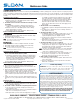
The information contained in this document is subject to change without notice. Royal & Regal Hydraulic Flushometer M.G. – Rev. 2 (10/08) Code No. 0816319
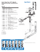
Maintenance Guide
ABBREVIATIONS:
CP = Chrome plated
RB = Rough brass
gpf = gallons per flush
Lpf = Liters per flush
LC = Low consumption
WH = Wheel handle
3
2
1
4
12
Includes
Item No. 4
13
17
18
14
15
16
Valve Body
‡
5
6
7B
7A
8
9A
9B
10
11A
11B
25
23
24
20
21
22
19
(See Inside
Parts Kit
Chart)
Royal Models
Royal — item 3 — Dual Filtered Diaphragm™ Assembly
Sold ONLY in ROYAL Performance™ Kits
ROYAL Performance™ KIT includes: Dual Filtered Diaphragm Assembly (item 3);
High Back Pressure Vacuum Breaker Repair Kit (item 4); and one Tailpiece O-Ring (item 7A)
Diaphragm Only KIT includes: Dual Filtered Diaphragm Assembly (item 3) ONLY
Performance KIT DIAPHRAGM Only Kit
Code No. Kit No. Code No. Kit No. Flush Volume Use with
Relief
Valve
Refill
Head †
Flow Ring
A 3301070 A-1101-A 3301502 A-1041-A 1.6 gpf/6.0 Lpf
Low Consumption
Water Closets
Green Gray Smooth
B 3301071 A-1102-A 3301501 A-1038-A 3.5 gpf/13.2 Lpf
Water Saver Water
Closets
White Gray Smooth
C 3301072 A-1103-A 3301505 A-1044-A 2.4 gpf/9.0 Lpf
9 Liter European
Water Closets
Blue Gray Smooth
D 3301073 A-1106-A 3301504 A-1043-A 0.5 gpf/1.9 Lpf Wash Down Urinals Green Black
Smooth &
Slotted
E 3301074 A-1107-A 3301503 A-1042-A 1.0 gpf/3.8 Lpf
Low Consumption
Urinals
Green Black Slotted
F 3301075 A-1108-A 3301500 A-1037-A 1.5 gpf/5.7 Lpf Water Saver Urinals Black Black Smooth
† NOTE: Water Closet Refill Heads (Gray) have larger slots than Urinal Refill Heads (Black).
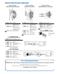
To Push Button Actuator
(See Actuator Variations
for applicable Push
Button style)
Hydraulic Inside Parts Repair Kits
Code No. Part No. Description
3318011 HY-1101-A Hydraulic Royal 1.6C
3318012 HY-1102-A Hydraulic Royal 3.5C
3318013 HY-1103-A Hydraulic Royal 2.4C
3318014 HY-1106-A Hydraulic Royal 0.5U
3318015 HY-1107-A Hydraulic Royal 1.0U
3318016 HY-1108-A Hydraulic Royal 1.5U
Comes with: Diaphragm, Actuator Cartridge Assembly, Tailpiece O-ring and Vacuum Breaker Assembly
HY-1101-A Shown
To identify the Flush Volume of a DUAL FILTERED DIAPHRAGM ASSEMBLY,
look at the color of the Relief Valve, the Refill Head and the shape of Flow
Ring.
‡ Part number varies with model variation. Consult factory.