
Installation Guide


Code No. 0816321
Rev. 3 (08/10)
INSTALLATION INSTRUCTIONS FOR BATTERY POWERED
SENSOR ACTIVATED LAVATORY FAUCETS
LIMITED WARRANTY
Sloan Valve Company warrants its EBF-615 and EBF-650 Faucets to be made of first class materials, free from defects of material or workmanship under normal
use and to perform the service for which they are intended in a thoroughly reliable and efficient manner when properly installed and serviced, for a period of three
years (1 year for special finishes) from date of purchase. During this period, Sloan Valve Company will, at its option, repair or replace any part or parts which prove
to be thus defective if returned to Sloan Valve Company, at customer’s cost, and this shall be the sole remedy available under this warranty. No claims will be allowed
for labor, transportation or other incidental costs. This warranty extends only to persons or organizations who purchase Sloan Valve Company’s products directly from
Sloan Valve Company for purpose of resale. This warranty does not cover the life of the batteries.
THERE ARE NO WARRANTIES WHICH EXTEND BEYOND THE DESCRIPTION ON THE FACE HEREOF. IN NO EVENT IS SLOAN VALVE COMPANY RESPONSIBLE FOR
ANY CONSEQUENTIAL DAMAGES OF ANY MEASURE WHATSOEVER.
PRIOR TO INSTALLATION
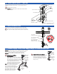
EBF-615
Pedestal,
Battery Powered,
Sensor Activated
Lavatory Faucet
EBF-650
4” Centerset,
Battery Powered,
Sensor Activated
Lavatory Faucet
Prior to installing the Sloan EBF-615 or EBF-650 faucet, install the items listed below. Also, refer to rough-in illustrations on Page 2.
• Lavatory/sink
• Drain line
• Hot and cold water supply lines or tempered water supply line
Mixing Valve
When installing the faucet with a Sloan Mixing Valve, these Installation Instructions AND the Installation Instructions packaged with the Mixing Valve
MUST
be followed.
Important:
•
ALL PLUMBING IS TO BE INSTALLED IN ACCORDANCE WITH APPLICABLE CODES AND REGULATIONS.
•
KEEP THREAD SEALANT OUT OF YOUR WATERWAY TO PREVENT COMPONENT PART DAMAGE! DO NOT USE ANY SEALANT ON COMPRESSION
FITTINGS. FOR THREADED PIPE FITTINGS, DO NOT APPLY SEALANT TO THE FIRST TWO “STARTER” THREADS.
•
FLUSH ALL WATER LINES UNTIL WATER IS CLEAR BEFORE CONNECTING SOLENOID TO SUPPLY STOPS.
DO NOT INSTALL THE BATTERIES UNTIL THE FAUCET IS COMPLETELY INSTALLED. If batteries are installed before sensor cable is connected to control module, the
faucet will not properly set the sensing range for the sink on which it is installed.
TOOLS REQUIRED FOR INSTALLATION
•
Open end wr
enc
hes f
or t
he f
ollowing hex
sizes:
1/2”, 9/16”, 5/8”,
11/
16”,
1”
•
B
asin
wrenc
h
•
Phillips head screwdriver, #2
•
Hammer (if installing plastic or hollow wall anchors to mount the
control module)
• Pliers
• 1/4" drill bit (if installing plastic wall anchors to mount the
control module)
• 5/16" drill bit (if installing hollow wall anchors to mount the
control module)
• 3/8" drill bit (if installing toggle nut anchors to mount control module)
Bak-Chek
®
Tee Usage
When connecting the EBF-615 or EBF-650 faucet to both hot and cold water supplies, a Bak-Chek
®
Tee is provided and required as illustrated in
Step 3. Water temperature can be controlled by adjusting the supply stops. When connecting the faucet to a single line water supply or a pre-
tempered water supply, a Bak-Chek
®
Tee is not required. A Bak-Chek
®
Tee is not required or provided when a Temperature Mixing Valve is included
with the faucet.