
Installation Sheet


3
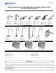
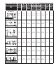
Quick Change
Battery Cartridge
Manifold Cover Assembly
Screws
A
nchors
Stainless Steel
Quick Connect Clips
Mounting Slot
Access
Solenoid
Stainless Steel
Quick Connect Clips
Anchors
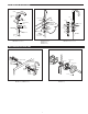
D. Connect water supply lines from the stops to the Filter “T” tting. If a mixing valve is being used, connect water supply lines to the mixing valve.
Connect the mixing valve to the single inlet lter tee using the supplied tting.
E. Attach sensor cable and solenoid cable to the appropriate connections on the manifold.
F. Insert the battery assembly.
G. This unit can use 4 (AA) batteries alone, or accept 6 VDC or 24 VAC power to function as a hardwired unit with battery back up.
H. If a 6 VDC plug-in transformer is used, plug it into the appropriate connection on the manifold to convert the faucet into a “plug-in with battery
back-up”.
I. If 24 VAC hardwires are being used, use the supplied adapter piece to connect the wires to the appropriate connection on the manifold.
J. If the unit contains an optional turbine, connect the plug from the turbine assembly into the appropriate connection on the manifold.
K. If ganging multiple units in a “daisy chain” conguration to a single power supply use the SFP35 gang adapter kit.
L. Inspect and tighten all connections. Place the manifold cover onto the unit.
M. Turn on water.
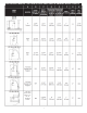
Control Module with
Double Inlet Tee Filter
Assembly.
Control Module with Single
Inlet Tee Filter Assembly
and Below Deck Mechanical
Mixing Valve (BDM)
Control Module with Single
Inlet Tee Filter Assembly
and Below Deck Thermostatic
Mixing Valve (BDT)
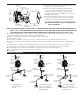
A. Ensure there is enough clearance for the exible supply hose from
the spout to connect to the control module
B. Secure control module to wall using the included mounting
accessories. The control module must be mounted on a level
vertical surface with the Sloan logo on the manifold facing
outwards on the top right side of the manifold. Do not mount the
manifold in any other position.
C. Insert the exible supply hose from the bottom of the spout into
the top of the mounted manifold.Insert the Filter “T” tting into
the bottom of the mounted manifold. Ensure that the stainless
steel clips on both the top and bottom of the manifold are secured.
NOTE: NEVER OPEN STAINLESS STEEL CLIPS WHEN WATER
SUPPLY IS TURNED ON.
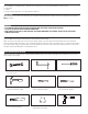
BELOW DECK CONFIGURATION
MANIFOLD INSTALLATION
NOTE: FOR UNITS WITH TURBINES, USE ONLY 0.5GPM / 1.9 LPM CONTROL BOXES WITH SPOUTS RATED FOR THE SAME FLOW AND USE
ONLY 1.5 GPM / 5.7 LPM CONTROL BOXES WITH SPOUTS RATED FOR THAT SAME FLOW. DO NOT USE THESE CONTROL BOXES ON
ANY OTHER FLOW RATES. CONTROL BOXES WITHOUT TURBINES MAY BE USED WITH ANY SPOUT UP TO 2.2 GPM / 8.3 LPM
Thermostatic
Mixing Valve
Mechanical
Mixing Valve
Y-Filter
Flexible
Supply
Hose
Flexible
Supply
Hose
Flexible
Supply
Hose
Faucet
Faucet
Faucet
Single Inlet
Filter Assembly
Single Inlet
Filter Assembly
Manifold
Assembly
Quick Connect
Clip
Stops
(not included)
Quick Connect
Clip
Quick Connect
Clip
Assembly
Quick Connect
Clip
Quick Connect
Clip
Quick Connect
Clip
Manifold
Assembly
Manifold
Assembly
Stops
(not included)
Stops
(not included)
Stops
(not included)
Stops
(not included)
Stops
(not included)
⅜” Supply Tube
(not included)
⅜” Supply
Tube
(not included)
⅜” Supply Tube
(not included)
⅜” Supply Tube
(not included)
⅜” Supply T
ube
(not included)
⅜” Supply Tube
(not included)