
User Manual


05K
J A C K A R O O
ATT
RC A1/8î TR S
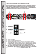
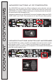
WARN IN G: D O N OT ENGAGE CABL E TEST WI TH
PO WE R R UN NING TH RU THE T EST
CA BL ES!
RC A1/8î TRS XL R
XL R
Cable
Test
Test
Tone
1 2 3 4 5 6 7 8
MIDI
MIDI
RJ45
RJ45
RJ11
RJ11
1/4î TRS
1/4î TRS
At tenua tor
Atten uator
05K
ATT
RC A1/8î TRS
RC A1/8î T RSXL R
XL R 1/4î TR S
1/4î TR S
2
Of f
5
5V d c
Of f
12V d c
9V a c
17 V ac
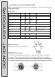
Voltage selector
3
4 6
7
8
Monitor selector
Voltage out
Max 500mA
BNC
BNC
100hz 1k 10k
MONITOR SPEAKER
L-RATT PASS
TR
GND LIFT
L-R
ATT PASS
TRLINK
Ba nan as:
48V PHANTOM POWER
SEND RE CEIVE
Co nti nuity t este r
Wi th B eep er & LE D
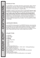
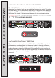
JACKAROO'functions:'continuity'tester
The JACKAROO features an on-board continuity tester, which allows you to
determine if an electrical path can be established between two points. Using the
included cables, you can easily test a wide variety of equipment, such as lamps,
illuminate if the signal is flowing properly between the two points being tested.
IMPORTANT:
MAKE SURE THE ITEM BEING TESTED IS NOT CONNECTED
TO ANY POWER SOURCE!
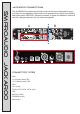
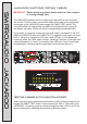
JACKAROO'FUNCTIONS:'Test'tone
SMPROAUDIO JACKAROO
05K
J A C K A R O O
ATT
RCA1/8î TRS
WARNING: DO NOT ENGAGE CABLE TEST WITH
POWER RUNN ING THR U THE TEST
CABL ES!
RCA1/8î TRS XLR
XLR
Cable
Test
Test
Tone
1 2 3 4 5 6 7 8
MIDI
MIDI
RJ45
RJ45
RJ11
RJ11
1/4î TRS
1/4î TRS
Attenuator
Attenuator
05K
ATT
RCA1/8î TRS
RCA1/8î TRSXLR
XLR 1/4î TR S
1/4î TR S
2
Of f
5
5V d c
Of f
12 V dc
9V a c
17 V ac
Voltage selector
3
4
6
7
8
Monitor selector
Voltage out
Max 500mA
BNC
BNC
100hz 1k 10k
MONITOR SPEAKER
L-RATT PASS
TRGND LIFT
L-RATT PASS
TRLINK
Ba nan as:
48V PHANTOM POWER
SEND RECEIVE
Co nti nui ty te ster
Wi th Be eper & L ED
Bananas:
Continuity tester
With Beeper & LE
D
Test
Tone
100hz 1k 10k
volume
single wires, PCB circuit boards, and the like. A buzzer will sound and the LED
The tone test generator can be set to 100Hz, 1kHz, or 10kHz. The output level
of the test tone can be adjusted via the screw located to the right of the tone
frequency selector switch.The test tone signal will appear only at the section A
output connectors unless the LINK switch (in the section B control panel) is set
to ON, in which case the tone will appear at both the A and B output connectors.
Note that the signal is carried only by pins 2, 3, and 4 of a connector, as pin 1
is ground.