SUNNY BOY STORAGE 3.8-US / 5.0-US / 6.0-US eManual ENGLISH Installation Manual FRANÇAIS Instructions d’installation ESPAÑOL Instrucciones de instalación SBSxx-US-10-IA-xx-12 | 111582-00.03 | Version 1.
Legal Provisions SMA Solar Technology AG ENGLISH Legal Provisions The information contained in these documents is the property of SMA Solar Technology AG. No part of this document may be reproduced, stored in a retrieval system, or transmitted, in any form or by any means, be it electronic, mechanical, photographic, magnetic or otherwise, without the prior written permission of SMA Solar Technology AG.
Table of Contents Table of Contents 1 2 Information on this Document................................................. 5 1.1 1.2 1.3 1.4 1.5 1.6 1.7 1.8 5 5 5 5 6 6 6 6 Validity ........................................................................................................................ Target Group.............................................................................................................. Content and Structure of this Document .............................................
Table of Contents ENGLISH 6.8 7 SMA Solar Technology AG DC Connection........................................................................................................... 6.8.1 Possible Connection ............................................................................... 6.8.1.1 Connection of Two Batteries .............................................. 6.8.1.2 Connection of a battery with a charging/discharging current limit of 10 A ...........................................................
1 1.1 ENGLISH 1 Information on this Document SMA Solar Technology AG Information on this Document Validity This document is valid for: • SBS3.8-US-10 (Sunny Boy Storage 3.8-US) from firmware version 1.50.10.R. • SBS5.0-US-10 (Sunny Boy Storage 5.0-US) from firmware version 1.50.10.R. • SBS6.0-US-10 (Sunny Boy Storage 6.0-US) from firmware version 1.50.10.R. 1.2 Target Group The tasks described in this document must only be performed by qualified persons.
1 Information on this Document SMA Solar Technology AG ENGLISH NOTICE Indicates a situation which, if not avoided, can result in property damage. 1.5 Symbols in the Document Symbol Explanation Information that is important for a specific topic or goal, but is not safety-relevant Indicates a requirement for meeting a specific goal Desired result A problem that might occur Example 1.
1 Information on this Document Title and information content Type of information "Approved batteries and battery communication connection" Overview of approved batteries Technical Information "Application for SMA Grid Guard Code" Form "Efficiency and Derating" Efficiency and derating behavior of the SMA inverters Technical Information ENGLISH SMA Solar Technology AG "Grid Support Utility Interactive Inverters" Technical Information Information about how to activate and to set the grid supporting
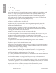
2 Safety ENGLISH 2 2.1 SMA Solar Technology AG Safety Intended Use The Sunny Boy Storage is an AC-coupled battery inverter for parallel grid and stand-alone mode operation. The Sunny Boy Storage converts the direct current supplied by a battery into gridcompliant alternating current.
2.2 IMPORTANT SAFETY INSTRUCTIONS SAVE THESE INSTRUCTIONS This section contains safety information that must be observed at all times when working on or with the product. The product has been designed and tested in accordance with international safety requirements. As with all electrical or electronical devices, there are residual risks despite careful construction.
2 Safety SMA Solar Technology AG ENGLISH WARNING Danger to life due to fire or explosion when batteries are fully discharged A fire may occur due to incorrect charging of fully discharged batteries. This can result in death or serious injury. • Before commissioning the system, verify that the battery is not fully discharged. • Do not commission the system if the battery is fully discharged. • If the battery is fully discharged, contact the battery manufacturer for further proceedings.
ENGLISH 2 Safety SMA Solar Technology AG NOTICE Damage to the enclosure seal in subfreezing conditions If you open the product or disconnect the Power Unit and Connection Unit when temperatures are below freezing, the enclosure seals can be damaged. Moisture can penetrate the product and damage it. • Only open the product if the ambient temperature is not below 0°C (32°F). • If a layer of ice has formed on the enclosure seal when temperatures are below freezing, remove it prior to opening the product (e.
2 Safety SMA Solar Technology AG ENGLISH Electrical installations (for North America) All installations must conform with the laws, regulations, codes and standards applicable in the jurisdiction of installation (e.g. National Electrical Code® ANSI/NFPA 70 or Canadian Electrical Code® CSA-C22.1.). • Before connecting the product to the utility grid, contact your local grid operator. The electrical connection of the product must be carried out by qualified persons only.
3 Scope of Delivery 3 ENGLISH SMA Solar Technology AG Scope of Delivery Figure 1 : Components included in the scope of delivery Position Quantity Designation A 1 Inverter B 1 Wall mounting bracket C 1 Cylindrical screw M5 x 60 D 1 Installation manual, production test report, supplementary sheet with the default settings E 1 4-pole terminal block for connecting a RS485 energy meter F 1 Terminal block for the AC connection G 1 Terminal block for connecting the outlet for secure po
4 Product Overview ENGLISH 4 SMA Solar Technology AG Product Overview 4.1 Product Description The Sunny Boy Storage uses the connected battery for the intermediate storage of excess PV energy in the SMA Flexible Storage System. For this purpose, the Sunny Boy Storage receives the feed-in data and purchased electricity data from the energy meter. This data is used by the Sunny Boy Storage to control the charging and discharging of the battery.
Position Designation F Type label The type label uniquely identifies the inverter. The type label must remain permanently attached to the product. You will find the following information on the type label: • Inverter device type (Model) • Serial number of the Power Unit (Serial No. Power Unit or S/N Power Unit) • Date of manufacture • Device-specific characteristics G Additional type label The additional type label must remain permanently attached to the product.
4 Product Overview ENGLISH Symbol SMA Solar Technology AG Explanation Inverter Together with the green LED, this symbol indicates the operating state of the inverter. Data transmission Together with the blue LED, this symbol indicates the status of the network connection. Equipment Grounding Terminal This symbol indicates the position for the connection of an equipment grounding conductor. The product is has no galvanic isolation. UL 1741 and CSA C22.2 No. 107.
4 Product Overview SMA Webconnect The inverter is equipped with a Webconnect function as standard. The Webconnect function enables direct data transmission between the inverters and Internet portals Sunny Portal and Sunny Places without any additional communication device and for a maximum of 1 inverters per visualized system. In PV systems with more than 1 inverters, there is the option of establishing data transmission between the inverters and Sunny Portal via the data logger (e.g.
4 Product Overview SMA Solar Technology AG ENGLISH Secure power supply operation In case of a grid failure, the secure power supply operation supplies the loads with energy from the battery. You can connect a standard outlet and a standard switch to the inverter. You can connect a load with a maximum of 16 A and 120 V to the outlet. The load is supplied with energy form the battery during grid failure. The switch is used to activate and deactivate secure power supply operation.
4 Product Overview connected can be supplied by the battery and supplemented with energy from the PV system. The charging of the battery is ensured by the existing PV system during battery-backup operation. The charging process of the battery (initiated by the PV system) can be deactivated via a certain parameter during battery-backup operation.
4 Product Overview SMA Solar Technology AG ENGLISH unable to provide energy. When the black-start switch is switched on manually, the energy from the auxiliary battery is made available in order to automatically switch the battery and therefore also the inverter from sleep mode to operation in order that the inverter can make energy available from the battery. You can stop the battery-backup operation by switching it off manually.
You can configure times and setpoints for the power drawn at the grid-connection point. When the loads require additional energy, the battery is discharged and the maximum value is kept constant at the grid-connection point This is based on the prerequisite that the battery is sufficiently charged. At times when the "Peak Load Shaving" function is not activated, the battery is charged or discharged correspondent to the increased self-consumption for the entire system.
4 Product Overview ENGLISH 4.4 SMA Solar Technology AG LED Signals LED signal Explanation The green LED is flashing (two seconds on and two seconds off) Waiting for feed-in conditions The conditions for feed-in operation are not yet met. As soon as the conditions are met, the inverter will start feed-in operation. The green LED is flashing (1.5 s on and 0.
4.
4 Product Overview SMA Solar Technology AG ENGLISH SMA Flexible Storage System with Battery-Backup Function Figure 5 : System design of a flexible storage system with battery-backup function (example) 24 SBSxx-US-10-IA-xx-12 Installation Manual
5 Mounting 5 5.1 ENGLISH SMA Solar Technology AG Mounting Requirements for Mounting Requirements for the Mounting Location: WARNING Danger to life due to fire or explosion Despite careful construction, electrical devices can cause fires. • Do not mount the product in areas containing highly flammable materials or gases. • Do not mount the product in potentially explosive atmospheres. ☐ A solid support surface must be available (e.g. concrete or masonry, free-standing constructions).
5 Mounting SMA Solar Technology AG ENGLISH Dimensions for mounting: Figure 8 : Position of the anchoring points(Dimensions in mm (in)) Recommended Clearances: To guarantee optimal operation and adequate heat dissipation for the inverter, the following requirements for clearances should be observed. This will prevent the inverter power output from being reduced due to excessive temperatures. However, smaller clearances are permitted without causing any risk.
Prescribed clearances in accordance with the National Electrical Code® or Canadian Electrical Code® CSA C22.1 Under certain conditions, the National Electrical Code® or the Canadian Electrical Code® CSA C22.1 specify greater clearances. • Ensure that the prescribed clearances in accordance with the National Electrical Code® or Canadian Electrical Code® CSA C22.1 are adhered to. ☐ Maintain the recommended clearances to walls as well as to other inverters or objects.
5 Mounting SMA Solar Technology AG ENGLISH CAUTION Risk of injury due to weight of product Injuries may result if the product is lifted incorrectly or dropped while being transported or when attaching it to or removing it from the wall mounting bracket. • Transport and lift the product carefully. Take the weight of the product into account. • Wear suitable personal protective equipment for all work on the product.
5 Mounting ENGLISH SMA Solar Technology AG 6. Hook the inverter into the wall mounting bracket. Here, the lugs on the rear side of the Power Unit must be hooked into the upper recesses and the lugs in the Connection Unit into the lower recesses in the wall mounting bracket. 7. Check whether the inverter is securely in place. If the Connection Unit can be moved forward, the lugs on the rear side of the Connection Unit are not hooked into the lower recesses in the wall mounting bracket.
6 Electrical Connection ENGLISH 6 SMA Solar Technology AG Electrical Connection 6.1 6.1.1 Overview of the Connection Area View from Below Figure 10 : Enclosure openings at the bottom of the inverter Position Designation A Enclosure opening for DC connection (for 21 mm (0.75 in) trade size conduits) B Enclosure opening for the battery communication cable (for 21 mm (0.75 in) trade size conduits) C Enclosure opening for the network cables and, if needed, for other data cables (for 21 mm (0.
6 Electrical Connection 6.1.
6 Electrical Connection SMA Solar Technology AG ENGLISH Position Designation L Equipment grounding terminal for equipment grounding conductors of the battery/batteries M Jacks BAT1 to BAT4 for the connection of the battery communication cable and the communication cable of the automatic transfer switch N Jack DISPLAY for the LED assembly connection in the enclosure lid of the Connection Unit O Fuses for DC connection P Auxiliary battery (3.
Load-break switch an cable protection: ☐ In PV systems with multiple inverters, protect each inverter with its own overcurrent protective device. Observe the maximum permissible fuse protection (see Section 10 "Technical Data", page 69). This will prevent residual voltage from being present at the corresponding conductor after disconnection. ☐ The load-break switch or circuit breaker must be listed (see National Electrical Code® ANSI/ NFPA 70) or Canadian Electrical Code® CSA C22.1).
6 Electrical Connection SMA Solar Technology AG ENGLISH 6. Guide the conductors from the conduit into the inverter. In the process, install the conductors in the inverter such that they do not come into contact with communication cables, the cable of the LED assembly or other live conductors. Lay the conductors as a loop if they are too long. 7.
ENGLISH 6 Electrical Connection SMA Solar Technology AG 15. Connect the conductors to the terminal block for the AC connection: • Connect the neutral conductor to the terminal block in accordance with the labeling. Insert the conductor into the corresponding terminal point (round opening) up to the stop. • Connect L1 and L2 to the terminal block in accordance with the labeling. Insert each conductor into the corresponding terminal point (round opening) up to the stop. 16.
6 Electrical Connection ENGLISH 6.3 SMA Solar Technology AG Connecting the Network Cables DANGER Danger to life due to electric shock in case of overvoltages and if surge protection is missing Overvoltages (e. g. in the event of a flash of lightning) can be further conducted into the building and to other connected devices in the same network via the network cables or other data cables if there is no surge protection.
ENGLISH 6 Electrical Connection SMA Solar Technology AG Procedure: DANGER 1. Danger to life due to electric shock • Disconnect the inverter from all voltage sources (see Section 8, page 66). 2. 3. 4. 5. 6. Remove the sealing plugs from the network connection opening on the inverter. Insert the conduit fitting into the opening and tighten from the inside using the counter nut. Attach the conduit to the conduit fitting. Lead one end of each network cable from the conduit into the inverter.
6 Electrical Connection SMA Solar Technology AG ENGLISH Requirements for data cable of battery: ☐ Twisted pair conductors ☐ Cable category: minimum CAT5e ☐ Shielding: yes ☐ Conductor cross-section: 0.25 mm² to 0.34 mm² (24 AWG to 16 AWG) ☐ Recommended number of conductor pairs: 4 ☐ External diameter: 6 mm to 8.5 mm (0.24 in to 0.
6 Electrical Connection ENGLISH SMA Solar Technology AG 8. If necessary, trim unused insulated conductors flush with the cable sheath or fold it over the cable sheath. 9. Connect the conductors of the communication cables to a 6-pole terminal block. Pay attention to the assignment of the terminal block and communication connection on the battery and/or automatic transfer switch and make sure that CAN L and CAN H consist of a pair of conductors. 10.
6 Electrical Connection SMA Solar Technology AG ENGLISH The energy meter and the electrical current strength transducers can also be mounted in the automatic transfer switch in battery-backup systems. Observe all manufacturer specifications and safety information when installing the energy meter. The energy meter is not a replacement for a revenue grade meter (RGM). The energy meter data may not be used for billing purposes.
6 Electrical Connection ENGLISH SMA Solar Technology AG 5. Unlock the terminal points of the 4-pole terminal block. 6. Connect the conductors of the RS485 communication cables to a 4-pole terminal block. To this end, insert the conductors into the terminal points and unlock the terminal points by pressing the lever down. Observe the terminal block assignment. 7. Ensure that the conductors are plugged into the terminal points tightly by pulling slightly on the conductors. 8.
6 Electrical Connection SMA Solar Technology AG ENGLISH 11. Configure the energy meter for operation with the inverter. When doing so, set the DIP switches 7 and 8 to ON (1) and the DIP switches 1 through 6 to 0. This ensures that the energy meter data can be transmitted to the inverter. 6.
Connect the outlet for secure power supply operation Requirements on・the conductors: ☐ The conductors with regards to its ampacity, rated temperatures, operating conditions and its power loss must be made in accordance with the local standards and the National Electrical Code® ANSI/NFPA 70 or the Canadian Electrical Code® CSA C22.1. ☐ Conductor type: copper wire ☐ The conductors must be made of solid wire, stranded wire or fine stranded wire. When using fine stranded wire, bootlace ferrules must be used.
6 Electrical Connection SMA Solar Technology AG ENGLISH 7. Plug the terminal block for connecting the outlet for secure power supply operation into the SPS slot in the inverter and tighten it with a flat-blade screwdriver (blade width: 4 mm (5/32 in)). 8. Ensure that the terminal block is securely in place. 9. Strip off the conductor insulation by max. 15 mm (0.59 in). 10. In the case of finely stranded wire, provide the conductors L and N with a bootlace ferrule. 11.
6 Electrical Connection ENGLISH SMA Solar Technology AG 14. Ensure the conductors are plugged into the terminal points (round openings) as far at is will go and not into the actuation shafts (rectangular openings). 15. Ensure that the terminal points are allocated to the correct conductors. 16. Ensure that the conductors are plugged completely into the terminal points up to their insulation. 17. Install outlet in desired position (e.g.
6 Electrical Connection ENGLISH 7. Stick the terminal block into the slot battery interface module in the inverter. SMA Solar Technology AG on the 8. Ensure that the terminal block is securely in place. 9. Ensure that all conductors are correctly connected. 10. Ensure that the conductors sit securely in the terminal points. Tip: To release the conductors from the terminal block, open the terminal points using a suitable tool. 11. Install switch in desired position (e.g.
7. Stick the terminal block into the slot battery interface module in the inverter. ENGLISH 6 Electrical Connection SMA Solar Technology AG on the 8. Ensure that the terminal block is securely in place. 9. Ensure that all conductors are correctly connected. 10. Ensure that the conductors sit securely in the terminal points. Tip: To release the conductors from the terminal block, open the terminal points using a suitable tool. 11. Install switch in desired position (e.g.
6 Electrical Connection SMA Solar Technology AG ENGLISH Procedure: The battery limited to a charging/discharging current of 20 A must be connected to the terminal blocks of the fuse holder A/B. The battery limited to a charging/discharging current of 10 A must be connected to the terminal blocks of the fuse holder C.
6 Electrical Connection Procedure: The wiring between the fuse holders A/B and DC terminal block must be changed: The conductors between the fuse holders A/B and terminal block B must be removed. The 25 A fuses in the fuse holders A/B must replaced with 15 A fuses. One battery must be connected to the terminal blocks A/B and the other to the terminal blocks of the fuse holders C. Figure 13 : Overview for connection of two batteries with a charging/discharging current limit of 10 A each 6.8.1.
6 Electrical Connection SMA Solar Technology AG ENGLISH The cylindrical fuse links of the fuse holders A/B and C must be replaced. The removal of the cylindrical fuse links must documented (e.g. on the label underneath the fuse holders). The battery must be connected to the terminal blocks of the fuse holder A/B. Figure 14 : Overview for connection of one battery with a charging/discharging current limit of 10 A (with black-start function) 6.8.1.
6 Electrical Connection ENGLISH SMA Solar Technology AG The battery with a charging/discharging current limit of 20 A must be connected to the terminal blocks of the fuse holder A/B. Figure 15 : Overview for connection of one battery with a charging/discharging current limit of 20 A 6.8.1.4 Connection of a battery with a charging/discharging current limit of 30 A Each DC terminal is designed for a maximum charging/discharging current of 10 A.
6 Electrical Connection SMA Solar Technology AG ENGLISH Two new fuse holders with a 40 A cylindrical fuse link must be installed and connected with DC terminal blocks. All terminals must be switched parallely. The battery must be connected to the terminal blocks of the new fuse holder. Figure 16 : Overview for connection of one battery with a charging/discharging current limit of 30 A 6.8.1.
6 Electrical Connection The outputs of the new fuse holders must be connected with DC terminal block A in the inverter. The 25 A cylindrical fuse links of the fuse holders A/B must be replaced with 15 A cylindrical fuse links. Two batteries must be connected to the fuse holders A/B and C inside the inverter. One battery must be connected to the new fuse holders outside the inverter. Figure 17 : Overview for connection of three batteries with a charging/discharging current limit of 10 A each 6.8.
6 Electrical Connection SMA Solar Technology AG ENGLISH Requirements on the DC conductors: ☐ The conductors with regards to its ampacity, rated temperatures, operating conditions and its power loss must be made in accordance with the local standards and the National Electrical Code® ANSI/NFPA 70 or the Canadian Electrical Code® CSA C22.1. ☐ The DC terminal block temperature rating is +90°C (+194°F). ☐ The maximum permitted temperature for the fuses of the DC connection of 105°C (221°F) must be observed.
6 Electrical Connection ENGLISH SMA Solar Technology AG 7. Ensure that the terminal points are allocated to the correct conductors. 8. Ensure that the conductors are plugged completely into the terminal points up to their insulation.
7 Commissioning ENGLISH 7 SMA Solar Technology AG Commissioning 7.1 Commissioning Procedure This section describes the commissioning procedure and gives an overview of the steps you must perform in the prescribed order. Procedure See 1. Commission the inverter. 2. Establish a connection to the user interface of the inverter. see section 7.
ENGLISH 7 Commissioning SMA Solar Technology AG Requirements: ☐ The AC circuit breaker must be correctly rated and mounted. ☐ The inverter must be correctly mounted. ☐ All conductors must be correctly connected. ☐ Unused enclosure openings must be sealed tightly with sealing plugs. Procedure: 1. Lead the enclosure lid to the Connection Unit and plug the ribbon cable into the socket on the communication assembly. 2. Ensure that the ribbon cable is securely plugged into the sockets at both ends. 3.
7 Commissioning ENGLISH 7.3 SMA Solar Technology AG Establishing a connection to the user interface 7.3.1 Establishing a Direct Connection via Ethernet Requirements: ☐ The product must be commissioned. ☐ An end device (e.g. computer) with an Ethernet interface must be available. ☐ The product must be connected directly to the end device. ☐ The respective latest version of one of the following web browsers must be installed: Chrome, Edge, Firefox, Internet Explorer or Safari.
7 Commissioning SSID, IP address and necessary passwords • SSID in WLAN: SMA[serial number] (e.g.
7 Commissioning SMA Solar Technology AG ENGLISH Web browser signals a security vulnerability 4. After the IP address has been confirmed by pressing the enter key, a message might appear indicating that the connection to the user interface of the inverter is not secure. SMA Solar Technology AG guarantees that calling up the user interface is secure. • Continue loading the user interface. ☑ The login page of the user interface opens. 7.3.
ENGLISH 7 Commissioning SMA Solar Technology AG Web browser signals a security vulnerability 2. After the IP address has been confirmed by pressing the enter key, a message might appear indicating that the connection to the user interface of the inverter is not secure. SMA Solar Technology AG guarantees that calling up the user interface is secure. • Continue loading the user interface. ☑ The login page of the user interface opens. 7.3.
7 Commissioning ENGLISH 2. SMA Solar Technology AG Web browser signals a security vulnerability After the IP address has been confirmed by pressing the enter key, a message might appear indicating that the connection to the user interface of the inverter is not secure. SMA Solar Technology AG guarantees that calling up the user interface is secure. • Continue loading the user interface. ☑ The login page of the user interface opens. 7.
7.5 ENGLISH 7 Commissioning SMA Solar Technology AG Selecting a configuration option After you have logged onto the user interface as Installer, the Configuring the Inverter page opens.
7 Commissioning SMA Solar Technology AG ENGLISH • Configuration with the installation assistant (recommended) • Manual configuration Adopting the Configuration from a File You can adopt the inverter configuration from a file. To do this, there must be an inverter configuration saved to a file. Procedure: 1. Select the configuration option Adopting configuration from a file. 2. Select [Browse...] and select the desired file. 3. Select [Import file].
4. To save the settings to a file, select [Export a summary] and save the file on your computer, tablet PC or smartphone. 5. To export all parameters and their settings, select [Export all parameters]. This exports all parameters and their settings into an HTML file. 6. To correct settings you made, select [Back], navigate to the desired step, correct settings and select [Save and continue]. 7. Once all settings are correct, select [Next] in the summary. ☑ The start page of the user interface opens.
8 Disconnecting the Inverter from Voltage Sources ENGLISH 8 SMA Solar Technology AG Disconnecting the Inverter from Voltage Sources Prior to performing any work on the inverter, always disconnect it from all voltage sources as described in this section. Always adhere to the prescribed sequence. NOTICE Destruction of the measuring device due to overvoltage • Only use measuring devices with a DC input voltage range of 600 V or higher. Procedure: 1.
9 Decommissioning the Inverter To decommission the inverter completely upon completion of its service life, proceed as described in this Section. CAUTION Risk of injury due to weight of product Injuries may result if the product is lifted incorrectly or dropped while being transported or when attaching it to or removing it from the wall mounting bracket. • Transport and lift the product carefully. Take the weight of the product into account.
9 Decommissioning the Inverter SMA Solar Technology AG ENGLISH 9. Seal all enclosure openings with sealing plugs. 10. Lead the enclosure lid to the Connection Unit and plug the ribbon cable into the socket on the communication assembly. 11. Ensure that the ribbon cable is securely plugged into the sockets at both ends. 12. Position the enclosure lid of the Connection Unit on the enclosure and tighten all 6 screws crosswise (TX 25, torque: 3 Nm ± 0.3 Nm (26.55 in-lb ± 2.65 in-lb)). 13.
10 Technical Data ENGLISH SMA Solar Technology AG 10 Technical Data 10.1 DC/AC 10.1.1 Sunny Boy Storage 3.8-US / 5.0-US AC connection SBS3.8-US-10 SBS5.0-US-10 Rated power 3800 W 5000 W Maximum apparent AC power 3800 VA 5000 VA Rated grid voltage 240 V 240 V AC voltage range 211 V to 264 V 211 V to 264 V 15.
10 Technical Data SMA Solar Technology AG ENGLISH SBS3.8-US-10 SBS5.0-US-10 Limits of accuracy of time measurement 0.001 s 0.001 s Operating range at AC power frequency 60 Hz 59.3 Hz to 60.5 Hz 59.3 Hz to 60.5 Hz > 3300 W > 4000 W 1 1 0.8overexcited to 0.8underexcited 0.8overexcited to 0.
10 Technical Data ENGLISH SMA Solar Technology AG 10.1.2 Sunny Boy Storage 6.0-US AC connection SBS6.
10 Technical Data SMA Solar Technology AG ENGLISH DC connection for battery Maximum DC voltage 600 V Voltage range* 100 V to 550 V DC rated voltage 360 V Maximum DC current 3 x 10 A Maximum short-circuit current 40 A Battery type** Li-ion Overvoltage category in accordance with IEC 60664-1 III * The charging and discharging voltage of the connected batteries must be in the range of 220 V and 500 V in order to make optimum use of the power of the inverter ** Only use batteries approved by SM
Rated grid voltage Triggering Triggering voltthreshold - Trig- age - Neutral gering voltages conductor Triggering voltage - L1 and L2 240 V 50 % 57.6 V to 62.4 V 115.2 V to 124.8 V max. 0.1602 s 88 % 103.2 V to 108.0 V 206.4 V to 216.0 V max. 2.002 s 110 % 129.6 V to 134.4 V 259.2 V to 268.8 V max. 1.001 s 120 % 141.6 V to 146.4 V 283.2 V to 292.8 V max. 0.
10 Technical Data ENGLISH Additional data volume when using the Sunny Portal live interface WLAN range in free-field conditions Quantity maximum detectable WLAN networks Topology SMA Solar Technology AG 600 kB/hour 100 m 32 Transformerless Cooling method Convection Enclosure type in accordance with UL 50E 3R Protection class 1 Grid configurations Approvals and national standards, as per 10/2017 240 V : 120 V split-phase system UL 1741, IEEE 1547 10.
ENGLISH 10 Technical Data SMA Solar Technology AG 10.
11 Compliance Information SMA Solar Technology AG ENGLISH 11 Compliance Information FCC Compliance This device complies with Part 15 of the FCC Rules and with Industry Canada licence-exempt RSS standard(s). Operation is subject to the following two conditions: 1. this device may not cause harmful interference, and 2. this device must accept any interference received, including interference that may cause undesired operation.
ENGLISH 12 Contact SMA Solar Technology AG 12 Contact If you have technical problems with our products, please contact the SMA Service Line. The following data is required in order to provide you with the necessary assistance: • Battery inverter: – Device type – Serial number – Firmware version – Event message – Mounting location and mounting height – Optional equipment, e.g.
Disposiciones legales SMA Solar Technology AG Disposiciones legales ESPAÑOL SMA Solar Technology AG es propietaria de todos los derechos de la información que se facilita en esta documentación. Queda prohibida la reproducción total o parcial de este documento, así como su almacenamiento en un sistema de recuperación y toda transmisión electrónica, mecánica, fotográfica, magnética o de otra índole sin previa autorización por escrito de SMA Solar Technology AG.