
Installation Guide
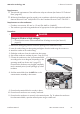
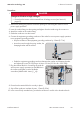
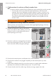
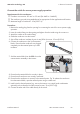
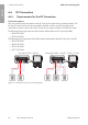

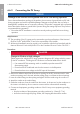
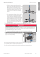
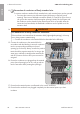
Table Of Contents
- Installation Manual
- Legal Provisions
- Table of Contents
- 1 Information on this Document
- 2 Safety
- 3 Scope of Delivery
- 4 Product Overview
- 5 Mounting
- 6 Electrical Connection
- 7 Commissioning
- 8 Disconnecting the Inverter from Voltage Sources
- 9 Decommissioning the Inverter
- 10 Technical Data
- 11 Compliance Information
- 12 Contact
- Instrucciones de instalación
- Disposiciones legales
- Índice
- 1 Indicaciones sobre este documento
- 2 Seguridad
- 3 Contenido de la entrega
- 4 Vista general del producto
- 5 Montaje
- 6 Conexión eléctrica
- 7 Puesta en marcha
- 8 Desconexión del inversor de la tensión
- 9 Puesta fuera de servicio del inversor
- 10 Datos técnicos
- 11 Información de cumplimiento
- 12 Contacto
- Instructions d’installation
- Dispositions légales
- Table des matières
- 1 Remarques relatives à ce document
- 2 Sécurité
- 3 Contenu de la livraison
- 4 Vue d’ensemble des produits
- 5 Montage
- 6 Raccordement électrique
- 7 Mise en service
- 8 Mise hors tension de l’onduleur
- 9 Mise hors service de l’onduleur
- 10 Caractéristiques techniques
- 11 Informations sur le respect des spécifications
- 12 Contact

6 Electrical Connection
SMA Solar Technology AG
Installation ManualSBxx-1SP-US-41-IA-xx-1048
6.6.2 Connecting the PV Array
NOTICE
Damage to the inverter due to ground fault on DC side during operation
Due to the transformerless topology of the product, the occurance of ground faults on DC side
during operation can lead to irreparable damage. Damages to the product due to a faulty or
damaged DC installation are not covered by warranty. The product is equipped with a protective
device that checks whether a ground fault is present during the starting sequence. The product is
not protected during operation.
• Ensure that the DC installation is carried out correctly and no ground fault occurs during
operation.
Requirements:
☐ The grounding of the PV system must be executed as per the specifications of the National
Electrical Code
®
ANSI/NFPA 70 and is the responsibility of the installer.
☐ All electrical installations must be carried out in accordance with the local standards and the
National Electrical Code
®
ANSI/NFPA 70 or the Canadian Electrical Code
®
CSA C22.1.
Procedure:
1.
DANGER
Danger to life due to high voltages
When exposed to sunlight, the PV array generates dangerous DC voltage which is present
in the DC conductors. Touching the DC conductors can lead to lethal electric shocks.
• If an external DC disconnecting switch is available, open the external DC
disconnecting switch.
• Ensure that the DC load-break switch on the inverter is in the O position.
• Ensure that there is no voltage on the DC inputs of the inverter.
2. Remove the adhesive tape from the enclosure opening for the DC connection and, if other
enclosure openings are to be used, take the sealing plugs out of these enclosure openings.
3. Insert the conduit fitting into the opening and tighten from the inside using the counter nut.
4. Attach the conduit to the conduit fitting.
5. Guide the conductors from the conduit into the inverter. In the process, lay the conductors in
the inverter such that they do not come into contact with the communication assembly.
6. Connect each equipment grounding conductor of the PV array to an equipment grounding
terminal:
• Strip the insulation of the equipment grounding conductor by 18mm (0.71in).
• Insert the screw through the spring washer, the clamping bracket and the washer.
ENGLISH