Installation Manual AUTOMATIC BACKUP UNIT BUUxx-US-10 SBS-ABU-xx-US-10 ENGLISH SBS-ABU-xx-US-IA-en-13 | Version 1.
Legal Provisions SMA Solar Technology AG Legal Provisions The information contained in these documents is the property of SMA Solar Technology America LLC. No part of this document may be reproduced, stored in a retrieval system, or transmitted, in any form or by any means, be it electronic, mechanical, photographic, magnetic or otherwise, without the prior written permission of SMA Solar Technology America LLC.
SMA Solar Technology AG Table of Contents Table of Contents 1 2 3 4 Information on this Document................................................. 4 1.1 1.2 1.3 1.4 1.5 1.6 4 4 4 4 5 5 Validity ........................................................................................................................ Target Group.............................................................................................................. Levels of Warning Messages .......................................
1 Information on this Document 1 SMA Solar Technology AG Information on this Document 1.1 Validity This document is valid for: • SBS-ABU-50-US-10 / BUUS1-US-10 • SBS-ABU-100-US-10 / BUUM2-US-10 • SBS-ABU-200-US-10 / BUUM3-US-10 1.2 Target Group The tasks described in this document must only be performed by qualified persons.
1 Information on this Document SMA Solar Technology AG Symbol Explanation A problem that might occur ✖ Example 1.5 Typographies in the Document Typography Use Example bold • • • • • > • Connects several elements to be selected • Select Settings > Date. [Button] [Key] • Button or key to be selected or pressed • Select [Enter]. 1.
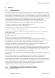
2 Safety 2 2.1 SMA Solar Technology AG Safety Intended Use The Automatic Backup Unit is an optional accessory for the Sunny Boy Storage inverter. It contains an automatic transfer switch, SMA Backup Unit Controller, overcurrent protection for the inverter(s) and optionally an integrated energy meter and current transformers. In the event of grid failure, the Automatic Backup Unit disconnects the PV system, loads and the Sunny Boy Storage from the utility grid and creates a battery-backup grid.
2 Safety SMA Solar Technology AG This section contains safety information that must be observed at all times when working on or with the product. The product has been designed and tested in accordance with international safety requirements. As with all electrical or electronical devices, there are residual risks despite careful construction.
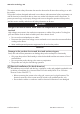
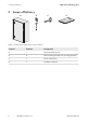
3 Scope of Delivery 3 SMA Solar Technology AG Scope of Delivery B A C D Figure 1: Components included in the scope of delivery Position Number Designation A 1 Automatic Backup Unit B 4 Wall mounting bracket incl.
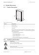
SMA Solar Technology AG 4 4 Product Overview Product Overview 4.1 Product Description Figure 2: Design of the Product Position Designation A Enclosure door B Connecting plate C Type label The type label clearly identifies the product. The type label must remain permanently attached to the product. You will find the following information on the type label: • Information of the manufacturer • Device type (Model) • Serial number (Serial No.
4 Product Overview Symbol SMA Solar Technology AG Explanation Observe the documentation Observe all documentation supplied with the product. UL 1741 and CSA C22.2 No. 107.1 are the standards applied by Underwriters Laboratories to the product to certify that it meets the requirements of the National Electrical Code®, the Canadian Electrical Code® and IEEE 1547.
SMA Solar Technology AG 5 5 System Structure System Structure The system consisting of battery inverters, PV inverters and an automatic transfer switch must be set up in accordance with the following schematic diagram. At the same time, the local regulations and standards must be observed.
5 System Structure SMA Solar Technology AG PV ARRAY DC+ cable DC– cable Line conductor Neutral conductor Grounding conductor CAN RS485 Speedwire/Ethernet Data cable SUNNY PORTAL PV-INVERTER ROUTER max 9.6 kW Power PROTECTIVE DEVICE max.50 A AUTOMATIC BACKUP UNIT PV-Inverter SMA BACKUP UNIT CONTROLLER L1 L2 N PE Autoformer Q5 PE CAN U Grid Grid U Loads F5 F202 Q1 F201 Energy Meter Grid Battery-Inverter L1 L2 N PE PROTECTIVE DEVICE SBSx.
5 System Structure SMA Solar Technology AG Delivery of overload current • During ramp-up: delivery of overload current for a maximum of one minute. Thereafter, the inverter shuts down. • During operation: overload current for a maximum of 500 ms. Thereafter, the inverter shuts down.
6 Mounting 6 6.1 SMA Solar Technology AG Mounting Requirements for Mounting WARNING Danger to life due to fire or explosion Despite careful construction, electrical devices can cause fires. • Do not mount the product in areas containing highly flammable materials or gases. • Do not mount the product in potentially explosive atmospheres. Mounting location: ☐ A solid, flat support surface must be available for mounting.
6 Mounting SMA Solar Technology AG Dimensions for mounting: Figure 5: Dimensions of the product(Dimensions in mm (in)) Installation Manual SBS-ABU-xx-US-IA-en-13 15
6 Mounting 6.2 SMA Solar Technology AG Mounting the product CAUTION Risk of injury due to weight of product Injuries may result if the product is lifted incorrectly or dropped while being transported or when attaching it to or removing it from the wall mounting bracket. • Transport and lift the product carefully. Take the weight of the product into account. • Wear suitable personal protective equipment for all work on the product.
7 Electrical Connection SMA Solar Technology AG 7 Electrical Connection 7.
7 Electrical Connection SMA Solar Technology AG Position Designation L Backup Unit Controller M Jack for connecting the communication cable to the battery inverter N The rotary switch S2100on the SMA Backup Unit Controller O The rotary switch S2101on the SMA Backup Unit Controller. 7.2 Inserting the Cables Always insert the cables into the product according to the following procedure.
7 Electrical Connection SMA Solar Technology AG Requirement for the communication cable: ☐ Twisted pair conductors ☐ Cable category: minimum CAT5e ☐ Shielding: yes ☐ Conductor cross-section: 0.25 mm² to 0.34 mm² (24 AWG to 16 AWG) ☐ Recommended number of conductor pairs: 4 ☐ External diameter: 6 mm to 8.5 mm (0.24 in to 0.33 in) ☐ Maximum cable length between battery and inverter and, in battery-backup systems, between automatic transfer switch and inverter: 10 m (33 ft) ☐ UV-resistant for outdoor use.
7 Electrical Connection SMA Solar Technology AG 6. Connect the conductors of the communication cables to the 6-pole terminal block. Pay attention to the assignment of the terminal block and communication connection on the battery inverter and make sure that CAN L and CAN H consist of a pair of conductors. 7. Ensure that the conductors are plugged into the terminal points tightly by pulling slightly on the conductors. 8.
SMA Solar Technology AG 7.4 7 Electrical Connection Connecting to utility grid and household distribution system Requirements: ☐ All electrical installations must be carried out in accordance with the local standards and the National Electrical Code® ANSI/NFPA 70 or the Canadian Electrical Code® CSA C22.1. ☐ The AC and DC electric circuits are isolated from the enclosure. If required by the National Electrical Code® ANSI/NFPA 70 or Canadian Electrical Code® CSA C22.
7 Electrical Connection SMA Solar Technology AG 3. Strip off the conductor insulation of L1, L2 and N (see Section 10 "Technical Data", page 27). 4. Connect the conductors L1, L2 and N of the utility grid to the terminal block -X200 in accordance with the labeling. Insert and press down the screwdriver into the square-shaped opening of the terminal block. 5. Connect the conductors L1, L2 and N of the household distribution system to the terminal block -X206 in accordance with the labeling.
7 Electrical Connection SMA Solar Technology AG 4. Connect the conductor N and the equipment grounding conductor of the PV inverter to the terminal blocks on the right side of the circuit breaker -F202 in accordance with the color coding. Insert each conductor into the corresponding terminal point (round opening) up to the stop. 5. Strip off the conductor insulation of L1 and L2 by 14.1 mm (9/16 in) each. 6.
7 Electrical Connection SMA Solar Technology AG Procedure: 1. Insert the communication cable (see Section 7.2, page 18). 2. Strip the communication cable 130 mm (5.12 in). 3. Trim the cable shield to a length of 20 mm (0.79 in) and fold it over the cable sheath. 4. Strip the insulation on the insulated conductors each by 6 mm (0.24 in). 5. If necessary, trim unused insulated conductors flush with the cable sheath or fold it over the cable sheath. 6.
SMA Solar Technology AG 8 8 Commissioning the battery-backup system Commissioning the battery-backup system 1. Make sure that the product is correctly mounted and connected. 2. Insert the dead front and tighten the seven screws using a flat-blade screwdriver (torque: 0.5 Nm (4.4 Ib-in)). 3. Lock up the product using the switch cabinet key. 4. Switch on the AC circuit breaker of the battery inverter and the PV system. 5. Reconnect to the utility grid. 6. Commission the inverters (see inverter manual). 7.
9 Compliance Information 9 SMA Solar Technology AG Compliance Information FCC Compliance This device complies with Part 15 of the FCC Rules and with Industry Canada licence-exempt RSS standard(s). Operation is subject to the following two conditions: 1. this device may not cause harmful interference, and 2. this device must accept any interference received, including interference that may cause undesired operation.
10 Technical Data SMA Solar Technology AG 10 Technical Data 10.1 SBS-ABU-50-US-10 / SBS-ABU-100-US-10 / SBSABU-200-US-10 Connection to utility grid and household distribution SBS-ABU-50-US-10 (BUUS1-US-10) Rated grid voltage SBS-ABU-100-US-10 SBS-ABU-200-US-10 (BUUM2-US-10) (BUUM3-US-10) 240 V 240 V 240 V Output nom.
10 Technical Data SMA Solar Technology AG SBS-ABU-50-US-10 (BUUS1-US-10) Clamping range of terminals L1/L2 Torque of terminals L1/ L2 SBS-ABU-100-US-10 SBS-ABU-200-US-10 (BUUM2-US-10) (BUUM3-US-10) 1 mm² to 25 mm² 1 mm² to 25 mm² 1 mm² to 25 mm² (18 AWG to 4 AWG) (18 AWG to 4 AWG) (18 AWG to 4 AWG) 2.8 Nm (24.8 in-lb) 2.8 Nm (24.8 in-lb) 2.8 Nm (24.8 in-lb) 10.2 General Data Width x height x depth Weight 500 mm x 700 mm x 250 mm (19.69 in x 27.56 in x 9.84 in) approx.
11 Contact SMA Solar Technology AG 11 Contact If you have technical problems with our products, please contact the SMA Service Line. The following data is required in order to provide you with the necessary assistance: • Device type • Serial number United States SMA Solar Technology Toll free for USA and US Territories America LLC +1 877-MY-SMATech (+1 877-697-6283) Rocklin, CA International: +1 916 625-0870 Canada SMA Solar Technology Toll free for Canada / Sans frais pour le Canada : Canada Inc.
www.SMA-Solar.