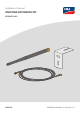
Installation Manual ANTENNA EXTENSION KIT EXTANT-US-40 ENGLISH EXTANT-US-40-IA-en-14 | Version 1.
Legal Provisions SMA Solar Technology AG Legal Provisions The information contained in these documents is the property of SMA Solar Technology AG. No part of this document may be reproduced, stored in a retrieval system, or transmitted, in any form or by any means, be it electronic, mechanical, photographic, magnetic or otherwise, without the prior written permission of SMA Solar Technology AG.
SMA Solar Technology AG Table of Contents Table of Contents 1 2 Information on this Document................................................. 4 1.1 1.2 1.3 1.4 1.5 1.6 4 4 4 4 5 5 Validity ........................................................................................................................ Target Group.............................................................................................................. Content and Structure of this Document ................................
1 Information on this Document 1 SMA Solar Technology AG Information on this Document 1.1 Validity This document is valid for: • EXTANT-US-40 (Antenna Extension Kit) 1.2 Target Group The tasks described in this document must only be performed by qualified persons.
1 Information on this Document SMA Solar Technology AG 1.5 Typographies in the Document Typography Use Example bold • • • • • > • Connects several elements to be selected • Select Settings > Date. [Button] [Key] • Button or key to be selected or pressed • Select [Enter]. # • Placeholder for variable components (e.g., parameter names) • Parameter WCtlHz.Hz# 1.
2 Safety 2 2.1 SMA Solar Technology AG Safety Intended Use The Antenna Extension Kit is an accessory set for SMA inverters: By installing the Antenna Extension Kit in an SMA inverter with WLAN interface, the inverter's radio range can be optimized within the WLAN network.
2 Safety SMA Solar Technology AG Any use of the product other than that described in the Intended Use section does not qualify as the intended use. The enclosed documentation is an integral part of this product. Keep the documentation in a convenient, dry place for future reference and observe all instructions contained therein.
2 Safety SMA Solar Technology AG NOTICE Damage to the enclosure seal in subfreezing conditions If you open the inverter when temperatures are below freezing, the enclosure seals can be damaged. This can lead to moisture entering the inverter. • Only open the inverter if the ambient temperature is not below 0°C (32°F). • If a layer of ice has formed on the enclosure seal when temperatures are below freezing, remove it prior to opening the inverter (e.g. by melting the ice with warm air).
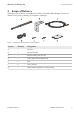
3 Scope of Delivery SMA Solar Technology AG 3 Scope of Delivery Check the scope of delivery for completeness and any externally visible damage. Contact your distributor if the scope of delivery is incomplete or damaged. Figure 1: Components included in the scope of delivery Position Quantity Designation A 1 Antenna B 1 Antenna bracket C 1 Antenna cable (3 m (9.
4 Mounting 4 SMA Solar Technology AG Mounting 4.1 Mounting position B A X2 ANT. X1 P20 VF-K ID: S P20 FCC9440A-K IC: B A . 30V Max DC USB MFR BAT Figure 2: Communication assembly in the inverter with mounting position for the antenna Position Designation A Communication assembly B Pin connector ANT.
4 Mounting SMA Solar Technology AG The mounting location of the antenna is crucial for the quality of the wireless connection. Radio waves are emitted in circles from the longitudinal side of the antenna. A circular dead spot begins at the tip of the antenna. If you place the receiver in this dead spot, the receiver cannot receive any radio waves from the antenna.
4 Mounting SMA Solar Technology AG Procedure: DANGER 1. Danger to life due to high voltages of the PV array When exposed to sunlight, the PV array generates dangerous DC voltage, which is present in the DC conductors and the live components of the inverter. Touching the DC conductors or the live components can lead to lethal electric shocks. • Prior to performing any work on the inverter, always disconnect the inverter from voltage sources on the AC and DC sides as described in the inverter manual.
4 Mounting SMA Solar Technology AG • Unscrew the swivel nut from the cable gland. 1 2 • Remove the two-hole cable support sleeve from the cable gland. • Route the antenna cable with the cable end with the plug through the swivel nut and the desired hole of the two-hole cable support sleeve. • Push the two-cable support sleeve along with the antenna cable back into the cable gland. Ensure that any unused openings of the two-hole cable support sleeve are sealed with sealing plugs.
4 Mounting SMA Solar Technology AG • Considering the dead spot of the antenna, move the antenna bracket to the desired position on the wall and hold it firmly. • Mark positions of drill holes if necessary and drill two holes with 6 mm (0.24 in) diameter each at the marked points and insert screw anchors. • Attach the antenna bracket to the wall with the screws. 5. Attaching the antenna cable and the antenna to the antenna bracket: • On the antenna cable, unscrew the counter nut approx. 5 mm (0.
4 Mounting SMA Solar Technology AG • Hand-tighten the antenna on the antenna extension cable plug. DANGER 6. Danger to life due to electric shock from touching an ungrounded product Touching an ungrounded product can cause a lethal electric shock. • Ensure that the product is integrated in the existing surge protection. 7. Close the inverter and recommission it (see inverter manual). ☑ The antenna is automatically recognized and activated by the inverter.
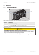
5 Troubleshooting 5 SMA Solar Technology AG Troubleshooting Problem Cause and corrective measures The radio range has not im- The problem can be caused by one of the following: proved despite the antenna. • The inverter has not recognized the antenna automatically. • The antenna is not installed correctly or an unapproved antenna has been used. • The receiver is placed in the dead spot.
6 Decommissioning SMA Solar Technology AG 6 Decommissioning 6.1 Removing the Antenna Required tools: ☐ Long-nosed pliers Procedure: DANGER 1. Danger to life due to high voltages of the PV array When exposed to sunlight, the PV array generates dangerous DC voltage, which is present in the DC conductors and the live components of the inverter. Touching the DC conductors or the live components can lead to lethal electric shocks.
6 Decommissioning 6.2 SMA Solar Technology AG Disposing of the Product • Dispose of the product in accordance with the locally applicable disposal regulations for electronic waste.
7 Contact SMA Solar Technology AG 7 Contact If you have technical problems with our products, please contact the SMA Service Line.
www.SMA-Solar.