SMA ROOFTOP COMMUNICATION KIT RoofCommKit-P1-US-IA-xx-11 | 105299-00.01 | Version 1.
ENGLISH Installation Manual................................................................... 3 ESPAÑOL Instrucciones de instalación ...................................................31 FRANÇAIS Instructions d’installation........................................................
Legal Provisions No part of this document may be reproduced, stored in a retrieval system, or transmitted, in any form or by any means, be it electronic, mechanical, photographic, magnetic or otherwise, without the prior written permission of SMA Solar Technology America LLC. Neither SMA Solar Technology America LLC nor SMA Solar Technology Canada Inc.
Important Safety Instructions SMA Solar Technology America LLC ENGLISH Status: 6/12/2017 Copyright © 2017 SMA Solar Technology America LLC. All rights reserved. Important Safety Instructions SAVE THESE INSTRUCTIONS This manual contains important instructions for the following products: • RoofCommKit-P1-US (SMA Rooftop Communication Kit) • SB3.0-1SP-US-40 (Sunny Boy 3.0-US) • SB3.8-1SP-US-40 (Sunny Boy 3.8-US) • SB5.0-1SP-US-40 (Sunny Boy 5.0-US) • SB6.0-1SP-US-40 (Sunny Boy 6.0-US) • SB7.
General Warnings Warnings on this Product The following symbols are used as product markings with the following meanings. Warning regarding dangerous voltage The product works with high voltages. All work on the product must only be performed as described in the documentation of the product. Beware of hot surface The product can become hot during operation. Do not touch the product during operation. Observe the operating instructions Read the documentation of the product before working on it.
Table of Contents SMA Solar Technology America LLC ENGLISH Table of Contents 1 2 Information on this Document................................................. 7 1.1 1.2 1.3 1.4 Validity ............................................................................................... Target Group ..................................................................................... Symbols.............................................................................................. Typographies ........
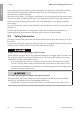
1 Information on this Document ENGLISH SMA Solar Technology America LLC 1 Information on this Document 1.1 Validity This document describes the assembly and installation of approved accessories in SMA inverters. This document supplements the documents that are enclosed with each inverter and does not replace any locally applicable codes or standards. Read and observe all documents supplied with the inverter. This document applies to the SMA Rooftop Communication Kit (RoofCommKit-P1-US). 1.
1 Information on this Document ENGLISH Typography Use SMA Solar Technology America LLC Example > • Connects several elements to be selected • Select Settings > Date. [Button] • Button to be selected or pressed • Select [Next].
2 Safety ENGLISH SMA Solar Technology America LLC 2 Safety 2.1 Intended Use The SMA Rooftop Communication Kit is a communication set for TS4-R module technology components. The SMA Rooftop Communication Kit allows installation of the Cloud Connect Advanced in an SMA inverter. SUNNY PORTAL PV GENERATOR ... GATEWAY (GTWY) TS4-R INTERNET ... ...
2 Safety SMA Solar Technology America LLC ENGLISH Use this product only in accordance with the information provided in the enclosed documentation and with the locally applicable standards and directives. Any other application may cause personal injury or property damage. Alterations to the product, e.g. changes or modifications, are only permitted with the express written permission of SMA. Unauthorized alterations will void guarantee and warranty claims and in most cases terminate the operating license.
ENGLISH 2 Safety SMA Solar Technology America LLC Damage to seals on the enclosure lids in subfreezing conditions If you open the enclosure lids when temperatures are below freezing, the enclosure seals can be damaged. This can lead to moisture entering the inverter. • Only open the enclosure lids if the ambient temperature is not below 0°C (32°F) • If a layer of ice has formed on the seal of the lid when temperatures are below freezing, remove it prior to opening the enclosure lids (e.g.
2 Safety SMA Solar Technology America LLC ENGLISH After installation of the Rooftop Communication Kit, the secure power supply operation is no longer supported. The Rooftop Communication Kit supports the Rapid Shutdown function. A Rapid Shutdown is triggered in the event of a grid failure or an interruption of the AC supply of the inverter and Cloud Connect Advanced. Thus the supply of the outlet for secure power supply operation is no longer possible.
3 Scope of Delivery ENGLISH SMA Solar Technology America LLC 3 Scope of Delivery A * L N TOP C B D E F Figure 2 : Components included in the scope of delivery Position Quantity Designation A 1 Package of Tigo Energy: Cloud Connect Advanced, gateway, WLAN antenna, documentation, screwdriver, warning label, power supply unit, DIN rail* B 1 Network cables C 1 DIN rail D 2 Bolt M5 x 6 E 1 Insulating hose F 1 Installation Manual * The DIN rail from the Tigo Energy package is not
4 Mounting SMA Solar Technology America LLC ENGLISH 4 Mounting 4.1 Mounting Position and Cable Route DC-in AC-out COM A M1 X1 SPS B M2 X2 ANT. C FCC ID: SVF-KP20 IC: 9440A-KP20 DISPLAY Max.
4 Mounting 4.2 ENGLISH SMA Solar Technology America LLC Mounting the Rooftop Communication Kit Procedure: Danger to life due to electric shock • Disconnect the inverter from all voltage sources (see inverter manual). 1. Tighten the DIN rail to the tap holes in the inverter using both M5 x 6 screws and a Torx screwdriver (TX 25) (torque: 2,8 Nm ± 0,2 Nm (24,78 in-lb ± 1.77 in-lb).
5 Connection SMA Solar Technology America LLC ENGLISH 5 Connection 5.1 Installing the Power Supply Unit Procedure: • Connect the power supply line (120 VAC) to the power supply unit. • Connect the power supply line (24 VDC) of the power supply unit to Cloud Connect Advanced. • Mount the power supply unit on the DIN rail.
ENGLISH 5 Connection SMA Solar Technology America LLC Risk of fire due to connection of the power supply unit to the AC connection of the inverter The AC connection of the inverter can not be used for the supply of the power supply unit for the Rooftop Communication Kit. The sole purpose of the AC connection is to feed the alternating current generated by the inverter into the utility grid. By additionally connecting the power supply unit, a fire may occur.
5 Connection SMA Solar Technology America LLC ENGLISH 8. Connect the end of the conductor to the circuit breaker or the overcurrent protective device. 9. Attach the warning label from outside and clearly visible at the AC distribution board.
6. Connect the positive and negative terminal to the terminal block in accordance with the labeling. + ENGLISH 5 Connection SMA Solar Technology America LLC _ +_ + 7. Ensure that the conductors sit securely in the terminal point of the terminal block. 8. Plug the terminal block into the jack POWER of the Cloud Connect Advanced.
5 Connection SMA Solar Technology America LLC ENGLISH Connecting the Network Cables 1. Plug one end of the network cable into the network port B of the communication assembly. 100-240 L A VAC 0.88 50/6 A 0Hz N B A B D-IN 2. Plug the other end of the network cable into the network port at the bottom of the Cloud Connect Advanced. FCC IC: 94ID: SV 40A F-KP -KP2 0 + _ DC OK SPS TOP + +V DAJ 100-240 L A VAC 0.
5 Connection ENGLISH SMA Solar Technology America LLC Cabling plan of the gateways: _ + BA _ + BA _ + BA _ + BA _ + BA _ + BA _ + BA _ + BA _ + BA Figure 5 : Cabling plan of the gateways with Cloud Connect Advanced Cable requirements: ☐ Number of insulated conductor pairs and insulated conductor cross-section: at least 2 x 2 x 0.22 mm² (2 x 2 x 22 AWG) ☐ The conductor must be shielded. ☐ The conductors must be twisted-pair.
5 Connection SMA Solar Technology America LLC ENGLISH 5. Pull the terminal block for the connection of the gateway out of the jack GATEWAY of the Cloud Connect Advanced. X2 + FCC IC: 94ID: SV 40A F-KP -KP20 _ TOP DC OK + +V DA J 100-24 0VA C 0.88A 50/60H z L A N B 6. Connect the conductors to the terminal point of the terminal block and tighten the screw terminals with the screwdriver. X1 X2 DISP LAY + FCC IC: 94ID: SV 40A- F-KP KP20 _ TOP DC OK + +V DAJ Max .
ENGLISH 5 Connection SMA Solar Technology America LLC 1. Remove the conductors L1, L2 and, if necessary, N from the terminal blocks of the terminal points AC-out (round opening). To release the conductors from the terminal points, open the terminal points with a flat-blade screwdriver (blade width: 3.5 mm (0.14 in)). To open the terminal points, insert the flat-blade screwdriver into the actuation shaft of the terminal block (rectangular opening). 2.
5 Connection SMA Solar Technology America LLC ENGLISH • Place the conductors L1 and L2 into the terminal points in accordance with the labelling (round openings) L1 and L2 as far as possible. 5. Danger of fire due to incorrectly plugged conductors By inserting the conductors into the actuation shafts, a fire may occur. • Ensure the conductors are plugged into the terminal points (round openings) as far at AC-out L1 N L2 is will go and not into the actuation shafts (rectangular openings).
6 Mounting the Gateway Mounting position ☐ The range of the wireless communication of the Gateway is approximately 15 m (50 ft). The Gateway should be mounted in the center of the PV array. 15 m (50 ft) Figure 6 : Mounting position of the Gateways in the PV array Procedure: 1. For installation on the back of the module proceed as follows: • Attach the bracket on the rear side. • Tighten the screw using suitable tools.
6 Mounting the Gateway SMA Solar Technology America LLC ENGLISH 2. When mounting on the frame construction, put the bracket of the Gateway on two screws that are anchored on the frame construction and attach the Gateway with suitable washers and nuts (hole diameter in the bracket of the Gateway: 9 mm (0.35 in)). The cable glands at the Gateway must face downwards. This will ensure that no moisture can penetrate the Gateway. 3. Ensure that the Gateway is securely in place. 4.
7 Commissioning the Rooftop Communication Kit ENGLISH SMA Solar Technology America LLC 7 Commissioning the Rooftop Communication Kit 1. Commission the inverter (see inverter manual). 2. Switch on the circuit breaker of the Rooftop Communication Kit and the Rapid Shutdown initiator. 3. Integrate the Cloud Connect Advanced into a network with Internet connection. • Integrate Cloud Connect Advanced via Ethernet into the network. For this, the inverter must be integrated via Ethernet into the network.
8 Disposing of the Product SMA Solar Technology America LLC ENGLISH 8 Disposing of the Product • Dispose of the product in accordance with the locally applicable disposal regulations for electronic waste.
9 Contact If you have technical problems with our products, please contact the SMA Service Line. We require the following information in order to provide you with the necessary assistance: • Inverters: – Serial number – Firmware version – Special country-specific settings (if applicable) • Serial number of Cloud Connect Advanced • Detailed description of the problem United SMA Solar Technology Toll free for USA, Canada and Puerto Rico / Llamada graStates/ Esta- America LLC tuita en EE. UU.
10 Compliance Information SMA Solar Technology America LLC ENGLISH 10 Compliance Information FCC Compliance This device complies with Part 15 of the FCC Rules. Operation is subject to the following conditions: 1. This device may not cause harmful interference, and 2. This device must accept any interference received, including interference that may cause undesired operation.
SMA Solar Technology America LLC Disposiciones legales Queda prohibida la reproducción total o parcial de este documento, así como su almacenamiento en un sistema de recuperación y toda transmisión electrónica, mecánica, fotográfica, magnética o de otra índole sin previa autorización por escrito de SMA Solar Technology America, LLC. Ni SMA Solar Technology America, LLC ni SMA Solar Technology Canada Inc.
Instrucciones de seguridad importantes SMA Solar Technology America LLC SMA Solar Technology America LLC 6020 West Oaks Blvd. Suite 300 Rocklin, CA 95765 U.S.A. SMA Solar Technology Canada Inc. 2425 Matheson Blvd. E ESPAÑOL 7th Floor Mississauga, ON L4W 5K4 Canadá Versión: 12/06/2017 Copyright © 2017 SMA Solar Technology America LLC. Reservados todos los derechos.
SMA Solar Technology America LLC Símbolo Indicaciones generales Descripción ADVERTENCIA representa una indicación de seguridad que, de no ser observada, puede causar la muerte o lesiones físicas graves. PRECAUCIÓN representa una indicación de seguridad que, de no ser observada, puede causar daños materiales. Advertencias en este producto Estos símbolos se usan como marcas del producto, con estos significados. Advertencia de tensión peligrosa El producto funciona con alta tensión.
Índice SMA Solar Technology America LLC Índice 1 Indicaciones sobre este documento ....................................... 35 ESPAÑOL 1.1 1.2 1.3 1.4 2 Área de validez ................................................................................. Grupo de destinatarios ..................................................................... Símbolos............................................................................................. Marcas de texto ............................................
1 Indicaciones sobre este documento SMA Solar Technology America LLC 1 Indicaciones sobre este documento Área de validez Este documento describe la instalación de accesorios autorizados en un inversor SMA. Este documento es un complemento de aquellos facilitados con cada inversor y no sustituye las normativas y directivas locales vigentes. Lea y tenga en cuenta los documentos suministrados con el inversor. Este documento es válido para el SMA Rooftop Communication Kit (RoofCommKit-P1-US). 1.
1 Indicaciones sobre este documento 1.4 Marcas de texto Marca de texto Negrita SMA Solar Technology America LLC Uso • Conexiones Ejemplo ESPAÑOL • Ranuras • El valor puede leerse en el campo Energía. • Parámetros • Seleccione Ajustes. • Elementos de la interfaz de usuario • Introduzca 10 en el campo Minutos. • Elementos que deben seleccionarse • Elementos que deben introducirse > • Une varios elementos que deben seleccionarse. • Seleccione Ajustes > Fecha.
2 Seguridad SMA Solar Technology America LLC 2 Seguridad 2.1 Uso previsto GENERADOR FOTOVOLTAICO ESPAÑOL El SMA Rooftop Communication Kit es un kit de conmutación para los componentes de la técnica modular TS4-R. El SMA Rooftop Communication Kit permite la instalación del Cloud Connect Advanced en un inversor SMA. SUNNY PORTAL ... GATEWAY (GTWY) TS4-R INTERNET ... ...
2 Seguridad SMA Solar Technology America LLC ESPAÑOL Debe respetarse en todo momento el rango de funcionamiento admisible de todos los componentes. Utilice siempre el producto de acuerdo con las indicaciones de la documentación adjunta y observe las normativas y directivas locales vigentes. Cualquier otro uso puede causarle lesiones al usuario o daños materiales.
2 Seguridad SMA Solar Technology America LLC Si abre las tapas de la carcasa en caso de congelación, puede dañar la junta. Esto puede hacer que penetre humedad en el inversor. • Abra las tapas de la carcasa únicamente si la temperatura ambiente es inferior a 0 °C (32 °F). • Si tiene que abrir las tapas de la carcasa en condiciones de congelación, elimine antes de abrir la tapa de la carcasa cualquier posible formación de hielo en la junta (por ejemplo, derritiéndolo con aire caliente).
2 Seguridad SMA Solar Technology America LLC Después de la instalación del Rooftop Communication Kit, deja de ser compatible el funcionamiento de corriente de emergencia ESPAÑOL El Rooftop Communication Kit es compatible con la función Rapid Shutdown. El Rapid Shutdown se dispara en caso de apagón o interrupción de la alimentación de CA del inversor y del Cloud Connect Advanced. De esta manera la alimentación de una toma de pared para el funcionamiento de corriente de emergencia no es posible.
3 Contenido de la entrega SMA Solar Technology America LLC 3 Contenido de la entrega A ESPAÑOL * L N TOP C B D E F Imagen 8 : Contenido de la entrega Posición Cantidad Denominación A 1 Paquete de Tigo Energy: Cloud Connect Advanced, pasarela, antena WLAN, documentación, destornillador, adhesivo de advertencia, fuente de alimentación, carril DIN* B 1 Cable de red C 1 Carril DIN D 2 Tornillo M5x6 E 1 Tubo aislante F 1 Instrucciones de instalación * El carril DIN del paquete d
4 Montaje SMA Solar Technology America LLC 4 Montaje 4.1 Posición de montaje y recorrido de los cables DC-in AC-out COM ESPAÑOL A M1 X1 SPS B M2 X2 ANT. C FCC ID: SVF-KP20 IC: 9440A-KP20 DISPLAY Max.
4 Montaje SMA Solar Technology America LLC 4.2 Montaje del Rooftop Communication Kit Procedimiento: Peligro de muerte por descarga eléctrica 1. Atornille el carril DIN con los dos tornillos M5x6 y un destornillador Torx (TX 25) en los taladros roscados en el inversor (par de apriete: 2,8 Nm ± 0,2 Nm (24,78 in-lb ± 1,77 in-lb). Al hacerlo, la flecha encima de la inscripción "TOP" en el carril DIN debe señalar en dirección de la caja de bornes para la conexión de CA.
5 Conexión SMA Solar Technology America LLC 5 Conexión 5.1 Instalación de la fuente de alimentación Procedimiento: • Conecte el cable del suministro de corriente (120 VCA) a la fuente de alimentación. ESPAÑOL • Conecte el cable del suministro de corriente (24 VCC) de la fuente de alimentación al Cloud Connect Advanced. • Monte la fuente de alimentación en el carril DIN. Conecte el cable del suministro de corriente a la fuente de alimentación.
5 Conexión SMA Solar Technology America LLC Peligro de incendio en caso de conexión de la fuente de alimentación a la conexión de CA del inversor ESPAÑOL La conexión de CA del inversor no se puede utilizar para el suministro de la fuente de alimentación del Rooftop Communication Kit. La conexión de CA sirve exclusivamente para la inyección de la corriente alterna generada del inversor a la red pública. Con la conexión adicional de la fuente de alimentación pueden producirse incendios.
5 Conexión SMA Solar Technology America LLC 8. Conecte el extremo de los conductores en el disyuntor o en el dispositivo de protección contra sobrecorriente. 9. Coloque el adhesivo de advertencia en la parte exterior de la distribución CA de forma bien visible.
5 Conexión SMA Solar Technology America LLC 6. Conecte el polo positivo y negativo según la rotulación a la caja de bornes. + _ + 7. Asegúrese de que los conductores estén bien fijos en los puntos de embornaje de la caja de bornes. 8. Introduzca la caja de bornes en el conector hembra POWER del Cloud Connect Advanced. X2 FCC IC: 94ID: SV 40A F-KP -KP2 0 TOP A B + _ Montaje de la fuente de alimentación en el carril DIN • Coloque y encaje la fuente de alimentación en el carril DIN.
5 Conexión SMA Solar Technology America LLC Conexión del cable de red 1. Introduzca un extremo del cable de red en el conector hembra de red B del subgrupo de comunicación. 100-240 L A VAC 0.88 50/6 A 0Hz N B A B D-IN ESPAÑOL 2. Introduzca el otro extremo del cable de red en el conector hembra de red en la parte inferior del Cloud Connect Advanced. FCC IC: 94ID: SV 40A F-KP -KP2 0 + _ DC OK SPS TOP + +V DAJ 100-240 L A VAC 0.
5 Conexión SMA Solar Technology America LLC Asignación del cableado de las pasarelas: _ + BA _ + BA _ + BA _ + BA _ + BA _ + BA _ + BA _ + BA Imagen 11 : Asignación del cableado de las pasarelas con el Cloud Connect Advanced Requisitos del cableado: ☐ Número de pares de conductores y sección del conductor: mínimo 2 x 2 x 0,22 mm² (2 x 2 x 22 AWG) ☐ El conductor debe estar apantallado. ☐ Los conductores deben estar trenzados por pares.
5 Conexión SMA Solar Technology America LLC 5. Saque la caja de bornes para la conexión de la pasarela del conector hembra POWER del Cloud Connect Advanced. X2 + FCC IC: 94ID: SV 40A F-KP -KP20 _ TOP DC OK + +V DA J 100-24 0VA C 0.88A 50/60H z L A N B ESPAÑOL 6. En función de su rotulación, conecte los conductores al punto de embornaje de la caja de bornes y apriete los bornes roscados con el destornillador.
5 Conexión SMA Solar Technology America LLC 1. Extraiga los conductores L1, L2 y, en caso necesario, N de los puntos de embornaje en la caja de bornes AC-out (abertura redonda). Para soltar los conductores de los puntos de embornaje, abra estos últimos con un destornillador plano (hoja: 3,5 mm [0,14 in]). Para abrir los puntos de embornaje, introduzca el destornillador plano en el orificio de accionamiento de la caja de bornes (abertura rectangular). 3. Coloque el tubo aislante en los conductores de CA.
5 Conexión SMA Solar Technology America LLC • Si hay disponible un conductor neutro, este debe introducirse hasta el tope en el punto de embornaje N (abertura redonda). SP AC-out L1 N L2 ESPAÑOL • En función de su inscripción, introduzca los conductores L1 y L2 hasta el tope en los puntos de embornaje (aberturas redondas) L1 y L2. 5. Peligro de incendio debido a conductores introducidos incorrectamente Si se introducen los conductores en los orificios de accionamiento puede originarse un incendio.
6 Montaje de la pasarela SMA Solar Technology America LLC 6 Montaje de la pasarela ESPAÑOL Posición de montaje ☐ El alcance de la comunicación inalámbrica es de aprox. 15 m (50 ft). La pasarela debe montarse en el centro del campo de energía fotovoltaica. 15 m (50 ft) Imagen 12 : Posición de montaje de la pasarela en el campo de energía fotovoltaica Procedimiento: 1. Para el montaje en la parte trasera del módulo, proceda como se describe a continuación: • Inserte el soporte en la parte trasera.
6 Montaje de la pasarela SMA Solar Technology America LLC ESPAÑOL 2. Para el montaje en el bastidor, coloque el soporte de la pasarela en 2 tornillos anclados en el bastidor y fije allí la pasarela con arandelas y tuercas apropiadas (diámetro de orificio en el soporte de la pasarela: 9 mm (0,35 in). Al hacerlo, los racores atornillados para cables en la pasarela deben mirar hacia abajo. De esta manera se garantiza que no pueda entrar humedad en la pasarela. 3.
SMA Solar Technology America LLC 7 Puesta en servicio del Rooftop Communication Kit 7 Puesta en servicio del Rooftop Communication Kit 1. Ponga en funcionamiento el inversor (consulte las instrucciones del inversor). 2. Conecte el disyuntor del Rooftop Communication Kit y del emisor de pulsos de Rapid Shutdown. • Integre el Cloud Connect Advanced mediante ethernet a la red. Para ello, el inversor debe estar integrado mediante ethernet a la red.
8 Eliminación del producto SMA Solar Technology America LLC 8 Eliminación del producto • Deseche el producto conforme a las disposiciones vigentes sobre eliminación de residuos electrónicos.
9 Contacto SMA Solar Technology America LLC 9 Contacto Si surge algún problema técnico con nuestros productos, póngase en contacto con el Servicio Técnico de SMA.
10 Información de cumplimiento SMA Solar Technology America LLC 10 Información de cumplimiento FCC Compliance This device complies with Part 15 of the FCC Rules. Operation is subject to the following conditions: 1. This device may not cause harmful interference, and ESPAÑOL 2. This device must accept any interference received, including interference that may cause undesired operation.
SMA Solar Technology America LLC Dispositions légales Aucune partie du présent document ne peut être reproduite, stockée dans un système d’extraction de données ou transmise par quelque moyen que ce soit (électroniquement, mécaniquement, par photocopie ou par enregistrement) sans l’accord écrit préalable de SMA Solar Technology America, LLC. SMA Solar Technology America, LLC et SMA Solar Technology Canada Inc.
Consignes de sécurité importantes SMA Solar Technology America LLC SMA Solar Technology America LLC 6020 West Oaks Blvd. Suite 300 Rocklin, CA 95765 U.S.A. SMA Solar Technology Canada Inc. 2425 Matheson Blvd. E 7th Floor Mississauga, ON L4W 5K4 Canada État actuel : 12/06/2017 Copyright © 2017 SMA Solar Technology America LLC. Tous droits réservés.
SMA Solar Technology America LLC Symbole Consignes de sécurité importantes Description « DANGER » indique une consigne de sécurité dont le non-respect entraîne des blessures corporelles graves, voire la mort. « ATTENTION » indique une consigne de sécurité dont le non-respect peut entraîner des blessures corporelles légères ou de moyenne gravité. « PRUDENCE » indique une consigne de sécurité dont le non-respect peut entraîner des dommages matériels.
Avertissements d’ordre général SMA Solar Technology America LLC Avertissements d’ordre général FRANÇAIS Toutes les installations électriques doivent être réalisées conformément aux normes électriques en vigueur sur le site et au National Electrical Code® ANSI/NFPA 70 ou au Canadian Electrical Code® CSA C22.1.
SMA Solar Technology America LLC Table des matières Table des matières Remarques relatives à ce document....................................... 64 1.1 1.2 1.3 1.4 2 Champ d’application......................................................................... Groupe cible...................................................................................... Symboles............................................................................................ Formats...........................................
1 Remarques relatives à ce document SMA Solar Technology America LLC 1 Remarques relatives à ce document 1.1 Champ d’application Ce document décrit le montage et l’installation d’accessoires autorisés dans un onduleur SMA. Ce document complète les documents fournis avec chaque onduleur et ne remplace pas les normes ou directives applicables sur site. Lisez et suivez toute la documentation fournie avec l’onduleur. Ce document est valable pour le SMA Rooftop Communication Kit (RoofCommKit-P1-US). 1.
SMA Solar Technology America LLC 1 Remarques relatives à ce document Format Exemple Utilisation • Associe plusieurs éléments que vous devez sélectionner • Sélectionnez Réglages > Date. [Bouton] • Bouton que vous devez sélectionner ou actionner • Cliquez sur [Suivant].
2 Sécurité SMA Solar Technology America LLC 2 Sécurité 2.1 Utilisation conforme Le SMA Rooftop Communication Kit est un kit de communication pour les composants de technique modulaire TS4-R. Le SMA Rooftop Communication Kit permet de monter le Cloud Connect Advanced dans un onduleur SMA. GÉNÉRATEUR PHOTOVOLTAÏQUE SUNNY PORTAL ... GATEWAY (GTWY) TS4-R INTERNET FRANÇAIS ... ...
2 Sécurité SMA Solar Technology America LLC 2.2 Consignes de sécurité Ce chapitre contient des consignes de sécurité qui doivent être systématiquement respectées lors de toute opération effectuée sur et avec le produit. Lisez ce chapitre attentivement et respectez en permanence toutes les consignes de sécurité pour éviter tout dommage corporel et matériel, et garantir un fonctionnement durable du produit.
2 Sécurité SMA Solar Technology America LLC Risque d’endommagement du joint des couvercles du boîtier en raison du gel Si vous ouvrez les couvercles du boîtier en cas de gel, le joint peut être endommagé. De l’humidité peut donc pénétrer dans l’onduleur. • N’ouvrez les couvercles du boîtier que si la température ambiante n’est pas inférieure à 0 °C (32 °F).
2 Sécurité SMA Solar Technology America LLC Le mode d’alimentation de secours n’est plus supporté après le montage du Rooftop Communication Kit Le Rooftop Communication Kit supporte la fonction Rapid Shutdown. En cas de panne du réseau ou d’une coupure de la tension AC de l’onduleur et du Cloud Connect Advanced, la fonction Rapid Shutdown est déclenchée. L’alimentation d’une prise de courant pour le mode d’alimentation de secours n’est donc plus assurée.
3 Contenu de la livraison SMA Solar Technology America LLC 3 Contenu de la livraison A * L N TOP FRANÇAIS C B D E F Figure 14 : Éléments du contenu de livraison Position Quantité Désignation A 1 Pack de Tigo Energy : Cloud Connect Advanced, passerelle, antenne de réseau local sans fil, documentation, tournevis, autocollants d’avertissement, bloc d’alimentation, rail DIN* B 1 Câbles réseau C 1 Rail DIN D 2 Vis M5 x 6 E 1 Gaine isolante F 1 Instructions d’installation * Le ra
4 Montage SMA Solar Technology America LLC 4 Montage 4.1 Position de montage et chemin des câbles DC-in AC-out COM A M1 X1 SPS B M2 X2 ANT. C FCC ID: SVF-KP20 IC: 9440A-KP20 DISPLAY MFR A B D-IN SPS D USB FRANÇAIS Max.
4 Montage 4.2 SMA Solar Technology America LLC Montage du Rooftop Communication Kit Procédure : Danger de mort par choc électrique • Mettez l’onduleur hors tension (voir instructions de l’onduleur). FRANÇAIS 1. Vissez le rail DIN avec les deux vis M5x6 et un tournevis Torx (TX 25) dans les trous filetés de l’onduleur (couple de serrage : 2,8 Nm ± 0,2 Nm (24,78 in-lb ± 1,77 in-lb).
5 Raccordement SMA Solar Technology America LLC 5 Raccordement 5.1 Installation du bloc d’alimentation Procédure : • Raccordez la ligne d’alimentation en courant (120 VAC) au bloc d’alimentation. • Raccordez la ligne d’alimentation en courant (24 VDC) du bloc d’alimentation au Cloud Connect Advanced. • Montez le bloc d’alimentation sur le rail DIN. Raccordement de la ligne d’alimentation en courant au bloc d’alimentation.
5 Raccordement SMA Solar Technology America LLC Risque d’incendie lié au raccordement du bloc d’alimentation au raccordement AC de l’onduleur Le raccordement AC de l’onduleur ne peut pas être utilisé pour alimenter le bloc d’alimentation du Rooftop Communication Kit. Le raccordement AC sert uniquement à injecter le courant alternatif généré de l’onduleur dans le réseau électrique public. Un incendie peut alors se produire lie au raccordement supplémentaire du bloc d’alimentation.
5 Raccordement SMA Solar Technology America LLC 8. Raccordez l’extrémité des conducteurs au disjoncteur miniature ou au dispositif de protection contre les surintensités. 9. Apposez l’autocollant d’avertissement à l’extérieur du distributeur AC de façon à ce qu’il soit bien visible.
5 Raccordement SMA Solar Technology America LLC 6. Raccordez le pôle positif et le pôle négatif à la plaque à bornes conformément à l’inscription. + _ +_ + 7. Assurez-vous que les conducteurs sont bien serrés dans les points de serrage de la plaque à bornes. 8. Enfichez la plaque à bornes dans l’embase POWER du Cloud Connect Advanced.
5 Raccordement SMA Solar Technology America LLC Raccordement du câble réseau 1. Enfichez une des extrémités du câble réseau dans la prise réseau B du groupe de communication. 100-240 L A VAC 0.88 50/6 A 0Hz N B A B D-IN FCC IC: 94ID: SV 40A F-KP -KP2 0 + _ DC OK TOP + +V DAJ FRANÇAIS 2. Enfichez l’autre extrémité du câble réseau dans la prise réseau sur la face inférieure du Cloud Connect Advanced. SPS 100-240 L A VAC 0.
5 Raccordement SMA Solar Technology America LLC Schéma de câblage des passerelles : _ + BA _ + BA _ + BA _ + BA _ + BA _ + BA _ + BA _ + BA _ + BA Figure 17 : Schéma de câblage des passerelles avec Cloud Connect Advanced FRANÇAIS Exigences en matière de câbles : ☐ Nombre de paires de conducteurs et section : au moins 2 x 2 x 0,22 mm² (2 x 2 x 22 AWG) ☐ Le conducteur doit être blindé. ☐ Les conducteurs doivent être à paires torsadées.
5 Raccordement SMA Solar Technology America LLC 5. Extrayez la plaque à bornes pour le raccordement de la passerelle de l’embase GATEWAY du Cloud Connect Advanced. X2 + FCC IC: 94ID: SV 40A F-KP -KP20 _ TOP DC OK + +V DA J 100-24 0VA C 0.88A 50/60H z L A N B 6. Raccordez les conducteurs conformément à l’inscription à la plaque à bornes et serrez les bornes à vis à l’aide de tournevis.
5 Raccordement SMA Solar Technology America LLC 1. Retirez les conducteurs L1, L2 et le cas échéant N des points de serrage de la plaque à bornes AC-out (orifice rond). Pour retirer les conducteurs des points de contacts, ouvrez les points de serrage à l’aide d’un tournevis à fente (largeur de lame : 3,5 mm (0,14 in)). Pour ouvrir les points de serrage, insérez le tournevis à fente dans l’orifice d’ouverture de la plaque à bornes (orifice carré). 2.
5 Raccordement SMA Solar Technology America LLC • S’il y a un conducteur neutre, introduisez le conducteur neutre jusqu’en butée dans le point de serrage (orifice rond) N. SP AC-out L1 N L2 • Introduisez les conducteurs L1 et L2 conformément à l’inscription jusqu’en butée dans les points de serrage (orifices ronds) L1 et L2. 5.
6 Montage de la passerelle SMA Solar Technology America LLC 6 Montage de la passerelle Position de montage ☐ La communication sans fil de la passerelle a une portée d’environ 15 m (50 ft). Il est conseillé de monter la passerelle au milieu du champ photovoltaïque. 15 m (50 ft) FRANÇAIS Figure 18 : Position de montage de la passerelle dans le champ photovoltaïque Procédure : 1. Pour un montage sur la face arrière du module, procédez comme suit : • Fixez le support sur la face arrière.
SMA Solar Technology America LLC 6 Montage de la passerelle 2. Pour un montage sur le cadre, positionnez le support de la passerelle sur le cadre en le plaçant sur deux vis ancrées dans le cadre et fixez-y la passerelle avec des rondelles et écrous adaptés (diamètre du trou dans le support de la passerelle : 9 mm (0,35 in). Les presse-étoupes sur la passerelle doivent alors pointer vers le bas. Cela permet d’éviter que de l’humidité pénètre dans la passerelle. 4.
7 Mise en service du Rooftop Communication Kit SMA Solar Technology America LLC 7 Mise en service du Rooftop Communication Kit 1. Mettez l’onduleur en service (voir les instructions de l’onduleur). 2. Enclenchez le disjoncteur miniature du Rooftop Communication Kit et l’émetteur d’impulsions Rapid Shutdown. 3. Intégrez le Cloud Connect Advanced dans un réseau avec accès à l’Internet : • Intégrez le Cloud Connect Advanced via Ethernet. Pour cela, l’onduleur doit être intégré dans le réseau via Ethernet.
SMA Solar Technology America LLC 8 Élimination du produit 8 Élimination du produit FRANÇAIS • Éliminez le produit conformément aux prescriptions d’élimination en vigueur pour les déchets d’équipements électriques et électroniques.
9 Contact SMA Solar Technology America LLC 9 Contact En cas de problèmes techniques concernant nos produits, prenez contact avec le Service en Ligne de SMA.
SMA Solar Technology America LLC 10 Informations sur le respect des spécifications 10 Informations sur le respect des spécifications FCC Compliance This device complies with Part 15 of the FCC Rules. Operation is subject to the following conditions: 1. This device may not cause harmful interference, and NOTE: This equipment has been tested and found to comply with the limits for a Class B digital device, pursuant to Part 15 of the FCC Rules.
www.SMA-Solar.