
Installation Manual
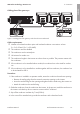
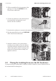

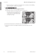

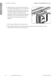
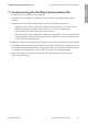


Table Of Contents
- 1 Information on this Document
- 2 Safety
- 3 Scope of Delivery
- 4 Mounting
- 5 Connection
- 6 Mounting the Gateway
- 7 Commissioning the Rooftop Communication Kit
- 8 Disposing of the Product
- 9 Contact
- 10 Compliance Information
- 1 Indicaciones sobre este documento
- 2 Seguridad
- 3 Contenido de la entrega
- 4 Montaje
- 5 Conexión
- 6 Montaje de la pasarela
- 7 Puesta en servicio del Rooftop Communication Kit
- 8 Eliminación del producto
- 9 Contacto
- 10 Información de cumplimiento
- 1 Remarques relatives à ce document
- 2 Sécurité
- 3 Contenu de la livraison
- 4 Montage
- 5 Raccordement
- 6 Montage de la passerelle
- 7 Mise en service du Rooftop Communication Kit
- 8 Élimination du produit
- 9 Contact
- 10 Informations sur le respect des spécifications
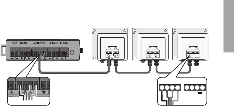
Cabling plan of the gateways:
B A
_
+B A
_
+ B A
_
+ B A
_
+B A
_
+ B A
_
+
B A
_
+B A
_
+
B
A
_
+
Figure 5 : Cabling plan of the gateways with Cloud Connect Advanced
Cable requirements:
☐ Number of insulated conductor pairs and insulated conductor cross-section: at least
2x2x0.22mm² (2x2x22AWG)
☐ The conductor must be shielded.
☐ The conductors must be twisted-pair.
☐ UV-resistant for outdoor use
☐ The conductors lengths in the inverter must be as short as possible. This prevents contact with
live conductors.
☐ If the conductor is to be installed without conduit, the conductor has to be suited for outdoor
use.
☐ If the conductor is to be installed in a conduit together with live conductors, the conductor has
to be insulated for 600V.
Procedure:
1. If the conductor is installed in a separate conduit, mount the conduit to the enclosure opening:
• Remove the sealing plugs from the network connection opening on the inverter.
• Insert the conduit fitting into the opening and tighten from the inside using the counter nut.
• Attach the conduit to the conduit fitting.
2. Guide the conductors from the conduit into the inverter. In the process, install the conductors in
the inverter such that they do not come into contact with AC conductor.
3. Strip off the conductor insulation by 7mm (0.28in).
4. In the case of fine stranded wire, provide the conductors with a bootlace ferrule.
5 Connection
SMA Solar Technology America LLC
Installation Manual 21RoofCommKit-P1-US-IA-xx-11
ENGLISH