
Installation Manual
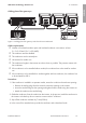
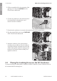

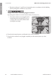

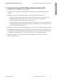

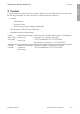

Table Of Contents
- 1 Information on this Document
- 2 Safety
- 3 Scope of Delivery
- 4 Mounting
- 5 Connection
- 6 Mounting the Gateway
- 7 Commissioning the Rooftop Communication Kit
- 8 Disposing of the Product
- 9 Contact
- 10 Compliance Information
- 1 Indicaciones sobre este documento
- 2 Seguridad
- 3 Contenido de la entrega
- 4 Montaje
- 5 Conexión
- 6 Montaje de la pasarela
- 7 Puesta en servicio del Rooftop Communication Kit
- 8 Eliminación del producto
- 9 Contacto
- 10 Información de cumplimiento
- 1 Remarques relatives à ce document
- 2 Sécurité
- 3 Contenu de la livraison
- 4 Montage
- 5 Raccordement
- 6 Montage de la passerelle
- 7 Mise en service du Rooftop Communication Kit
- 8 Élimination du produit
- 9 Contact
- 10 Informations sur le respect des spécifications

• Place the conductors L1 and L2 into the terminal points in accordance with the labelling
(round openings) L1 and L2 as far as possible.
5.
Danger of fire due to incorrectly plugged conductors
By inserting the conductors into the actuation shafts, a fire may occur.
• Ensure the conductors are plugged into the
terminal points (round openings) as far at
is will go and not into the actuation shafts
(rectangular openings).
AC-out
SPS
L1
L2
N
AC-out
SPS
L1
L2
N
6. Ensure that the terminal points are allocated to the correct conductors.
7. Ensure that the conductors are plugged completely into the terminal points up to their
insulation.
5 Connection
SMA Solar Technology America LLC
Installation ManualRoofCommKit-P1-US-IA-xx-1124
ENGLISH