
Installation Manual

9 Decommissioning the Inverter
To decommission the inverter completely upon completion of its service life, proceed as described
in this Section.
Risk of injury when lifting the inverter, or if it is dropped
The inverter weighs 26 kg (57.32 lbs). There is risk of injury if the inverter is lifted incorrectly or
dropped while being transported or when attaching it to or removing it from the wall mounting
bracket.
• Transport and lift the inverter carefully.
Procedure:
1.
Danger to life due to high voltages
• Disconnect the inverter from all voltage sources (see Section8, page57).
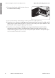
2. Remove the DC conductors from the DC-in connecting terminal plate. To release the
conductors from the terminals, open the terminals with a flat-blade screwdriver (blade width:
3.5mm (0.14in)). While doing so, only touch the connecting terminal plate on the black
enclosure.
3. Screw out the screws from the DC-in connecting terminal plate using a flat-blade screwdriver
(blade width: 3.5mm (0.14in)) and pull the connecting terminal plate out of the slot. While
doing so, only touch the connecting terminal plate on the black enclosure.
4. Remove the conductor L1, L2 and, if necessary, N from the AC-out connecting terminal plate.
To release the conductors from the terminals, open the terminals with a flat-blade screwdriver
(blade width: 3.5mm (0.14in)).
5. Screw out the screws from the AC-out connecting terminal plate using a flat-blade screwdriver
(blade width: 3.5mm (0.14in)) and pull the connecting terminal plate out of the slot.
6. Remove all equipment grounding conductors from the equipment grounding terminals. To do
this, remove each screw with a Torx screwdriver (TX 25) and remove the equipment grounding
conductor from the inverter; screw each screw back in with a Torx screwdriver (TX 25).
7. Remove all connection cables from the communication assembly.
Useful hint: To release the cables from the plugs, open the conduit entries using a suitable tool.
8. Remove all conduits with conductors from the inverter. To do this, screw the sleeves out of the
enclosure openings from the inside.
9. Seal all enclosure openings with sealing plugs.
10. Lead the enclosure lid to the Connection Unit and plug the display cable into the socket on the
communication assembly.
11. Ensure that the display cable is securely plugged into the sockets at both ends.
12. Position the enclosure lid of the Connection Unit on the enclosure and tighten all 6 screws
crosswise with a Torx screwdriver (TX 25) (torque 3Nm ± 0.3Nm (26.55in-lb ± 2.65in-lb)).
9 Decommissioning the Inverter
SMA Solar Technology America LLC
Installation manual 59SB5.0-6.0-1SP-US-40-IA-xx-10
ENGLISH