PV Inverters SUNNY BOY 1100 / 1200 / 1700 Installation Guide SB11_12_17-IEN100132 | IMEN-SB11_17 | Version 3.
SMA Solar Technology AG Table of Contents Table of Contents 1 1.1 1.2 1.3 1.4 Notes on this Manual. . . . . . . . . . . . . . . . . . . . . . . . . . . . . . Area of Validity. . . . . . . . . . . . . . . . . . . . . . . . . . . . . . . . . . . . . . Target Group . . . . . . . . . . . . . . . . . . . . . . . . . . . . . . . . . . . . . . . Additional Information . . . . . . . . . . . . . . . . . . . . . . . . . . . . . . . . Symbols Used . . . . . . . . . . . . . . . . . . . . . . . . . . . . . . . . . .
Table of Contents SMA Solar Technology AG 6.2 Blink Codes. . . . . . . . . . . . . . . . . . . . . . . . . . . . . . . . . . . . . . . . 29 7 7.1 7.2 Opening and Closing. . . . . . . . . . . . . . . . . . . . . . . . . . . . . 32 Opening the Sunny Boy . . . . . . . . . . . . . . . . . . . . . . . . . . . . . . 32 Closing the Sunny Boy . . . . . . . . . . . . . . . . . . . . . . . . . . . . . . . 33 8 8.1 Maintenance and Cleaning . . . . . . . . . . . . . . . . . . . . . . . .
SMA Solar Technology AG Notes on this Manual 1 Notes on this Manual This manual describes how to mount, install, commission and service the Sunny Boy 1100 (SB 1100), Sunny Boy 1200 (SB 1200) and Sunny Boy 1700 (SB 1700). Store this manual where it can be accessed at all times. 1.1 Area of Validity This manual applies to the following SMA inverters: • Sunny Boy 1100 (discontinued model), • Sunny Boy 1200 (available on request), • Sunny Boy 1700. 1.2 Target Group This manual is for qualified personnel.
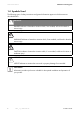
Notes on this Manual SMA Solar Technology AG 1.4 Symbols Used The following types of safety instructions and general information appear in this document as described below: DANGER! G DANGER indicates a hazardous situation which, if not avoided, will result in death or serious injury. WARNING! WARNING indicates a hazardous situation which, if not avoided, could result in death or serious injury.
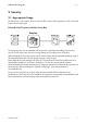
SMA Solar Technology AG Security 2 Security 2.1 Appropriate Usage The Sunny Boy is a PV inverter, which converts the DC current of the PV generator to AC current and feeds it into the public grid. Principle of a PV system with this Sunny Boy The Sunny Boy may only be operated with PV generators (modules and cabling) of protection class II. Do not connect any sources of energy other than PV modules to the Sunny Boy.
Security SMA Solar Technology AG Certified Countries The Sunny Boy 1100 / 1200 / 1700 (with according configuration) fulfill the requirements specified in the following standards and directives (dated: July/2009): • VDE 0126-1-1 (02.2006) • G83/1 (09.2003) • CER/06/190 (10.2006) • E 2750 (11.2004) • PPC (06.2006) • EN 50438 (12.2007) • C10/C11 (08.
SMA Solar Technology AG Security 2.2 Safety Instructions DANGER! Danger to life due to high voltages in the Sunny Boy! • All work on the Sunny Boy must only be carried out by qualified personnel. • The appliance is not to be used by children or persons with reduced physical, sensory or mental capabilities, or lack of experience and knowledge, unless they have been given supervision or instruction. • Children should be supervised to ensure that they do not play with the appliance.
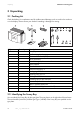
Unpacking SMA Solar Technology AG 3 Unpacking 3.1 Packing List Check the delivery for completeness and for visible external damage, such as cracks in the enclosure or in the display. Please contact your dealer if something is damaged or missing. Object A B C D E F G H I J K L M N O P Quantity 1 1 1 1 2 1 1 1 1 1 1 2 1 1 2 1 Description Sunny Boy Wall mounting bracket Electronic Solar Switch (ESS) Set of documents 1 installation guide, 1 user manual Socket element Threaded sleeve Pressure screw PG13.
SMA Solar Technology AG Installing the Device 4 Installing the Device 4.1 Selecting the Mounting Location DANGER! Danger to life due to fire or explosion! Despite careful construction, a fire can occur with electrical devices. • Do not mount the Sunny Boy on flammable construction materials. • Do not mount the Sunny Boy near highly flammable materials. • Do not mount the Sunny Boy in potentially explosive areas.
Installing the Device SMA Solar Technology AG • The ambient temperature should be below 40 °C to ensure optimal operation. • The Sunny Boy must be easy to remove from the mounting location at any time. • Do not expose the Sunny Boy to direct sunlight, so as to avoid power reduction due to excessive heating. • In a living area, do not mount the unit on plasterboard walls (or similar) in order to avoid audible vibrations.
SMA Solar Technology AG Installing the Device 4.2 Mounting the Sunny Boy with a Wall Mounting Bracket CAUTION! Risk of injury due to the heavy weight of the Sunny Boy! • Take the weight of the Sunny Boy of approx. 25 kg into account. • When mounting the bracket, use fastening material suitable for the material. 1. Use the wall mounting bracket as a drilling template and mark the position of the drill holes. 2. Attach the wall mounting bracket to the wall using appropriate screws and washers.
Installing the Device SMA Solar Technology AG 3. Use the upper mounting clips to fit the Sunny Boy in the wall mounting bracket so that it cannot be pushed out of the wall mounting bracket from the side. 4. Secure the Sunny Boy in position fastening the supplied M6x12 screw. 5. Check that the unit is securely in place. ☑ The Sunny Boy is now mounted on the wall.
SMA Solar Technology AG Electrical Connection 5 Electrical Connection NOTICE! Electrostatic discharges can damage the Sunny Boy! Internal components of the Sunny Boy can be irreparably damaged by static discharge. • Ground yourself before touching a component. 5.1 Overview of the Connection Area 5.1.1 Exterior View The following figure shows the assignment of the individual enclosure openings on the bottom of the Sunny Boy.
Electrical Connection SMA Solar Technology AG 5.1.2 Interior View The following diagram gives a schematic overview of the various components and connection points inside the Sunny Boy with the lid removed: Object A B C D E F G H I 16 Description Varistors, section 9.1.2 Connection area and sockets for communication (RS485, radio), section 5.4 Display PE (protective earth) connecting cable for cover Operating status LEDs Plug socket (AC), section 5.
SMA Solar Technology AG Electrical Connection 5.2 Connecting the Sunny Boy to the public grid (AC) Connection requirements of the grid operator Comply with the connection requirements of your utility operator. Cable Design The conductor cross-section should be dimensioned in a way that output losses do not exceed 1% at nominal power. Use "Sunny Design" (www.SMA.de/en/SunnyDesign) for this. The maximum cable lengths relative to the conductor cross-section are shown in the following table.
Electrical Connection SMA Solar Technology AG Load Disconnection Unit You must install a separate line circuit breaker for each inverter in order to ensure that the inverter can be securely disconnected under load. The maximal permissible rating is located in section 11 "Technical Data" (page 42) Detailed information and examples for the design of a line circuit breaker can be found in the Technical Information "Line Circuit Breaker" in the download area of www.SMA.de/en.
SMA Solar Technology AG Electrical Connection Overview AC connection socket Object A B C D E F Description Socket element Threaded sleeve Sealing ring PG13.5 Fastening case PG13.5 Pressure screw for PG13.5 (for cable diameters between 9 and 13.5 mm) Cable gland PG16 (for cable diameters between 13.5 and 17 mm) Connection Procedure 1. Choose an appropriate screw fitting for the AC cable. 2. Check the grid voltage and compare it with "VAC" on the type plate.
Electrical Connection SMA Solar Technology AG 7. Lead the pressure screw and/or cable gland and socket tube via the AC cable. Size used PG13.5 Procedure • Push the sealing ring into the fastening case. • Lead the pressure screw PG13.5 and the fastening case including the sealing ring via the AC cable. • Lead the threaded sleeve via the AC cable. PG16 • Lead the cable gland PG16 via the AC cable. • Lead the threaded sleeve via the AC cable. 8.
SMA Solar Technology AG Electrical Connection 13. Screw the threaded sleeve onto the socket element. 14. Screw the pressure screw tightly onto the threaded sleeve. Size used PG13.5 Procedure The fastening case along with the sealing ring is pressed into the threaded sleeve and can no longer be seen. PG16 ☑ AC connection socket has been screwed together. 15. Seal the socket element with the provided protecting cap if the Sunny Boy is not immediately connected. 16.
Electrical Connection SMA Solar Technology AG 5.3 Setting the Display Language You can set the language of the display using the switches on the underside of the display assemblies inside the Sunny Boy. Proceed as follows to do so: 1. Open the Sunny Boy as described in section 7.1 "Opening the Sunny Boy" (page 32). 2. Set the switches to the desired language as illustrated below. Language German English French Spanish Switch S2 B B A A Switch S1 B A B A 3. Close the Sunny Boy as described in section 7.
SMA Solar Technology AG Electrical Connection 5.5 Connecting the PV Generator (DC) Use of Adaptors Adaptors (branch connectors) are not to be visible or freely accessible in the immediate surrounding of the Sunny Boy. • The DC current flow may not be interrupted via adaptors. • Always disconnect the current flow first via the Electronic Solar Switch.
Electrical Connection SMA Solar Technology AG Connection Procedure DANGER! Danger to life due to high voltages in the Sunny Boy! • Before connecting the PV generator, ensure that the line circuit breaker is switched off. 1. Pull the Electronic Solar Switch downwards, slightly towards the wall. 2. Check the connection cables of the PV modules for correct polarity and compliance with the Sunny Boy's maximum input voltage of 400 V (DC).
SMA Solar Technology AG Electrical Connection 4. Connect faultless strings of the PV generator. 5. Close unused DC input sockets with the protective caps provided. 6. Check the Electronic Solar Switch for wear, as described in section 8.1 "Check the Electronic Solar Switch for wear" (page 35), and attach until it audibly locks into place.
Commissioning the Sunny Boy SMA Solar Technology AG 6 Commissioning the Sunny Boy 1.
SMA Solar Technology AG Commissioning the Sunny Boy 6.1 Display Feeding Operation After fault-free grid connection of the Sunny Boy, it takes approximately one minute until the following display messages are shown alternately. The display messages shown before only have the purpose of indicating the initialization of the Sunny Boy and the process of controlling whether the power supply requirements are fulfilled.
Commissioning the Sunny Boy SMA Solar Technology AG PV overvoltage !PV-Overvoltage! !DISCONNECT DC! NOTICE! Excessive DC input voltage can destroy the Sunny Boy! Immediately disconnect the Sunny Boy from the grid! 1. Turn off the line circuit breaker. 2. Remove the Electronic Solar Switch. 3. Disconnect the DC plug connectors. 1. Check DC voltage! Result ☑ The DC voltage is higher than the maximum input voltage. ☑ The DC voltage is lower than the maximum input voltage.
SMA Solar Technology AG Commissioning the Sunny Boy 6.2 Blink Codes Overview Green glows continuously Red is not glowing glows continuously Flashes quickly (3 x per second) Flashes slowly (1 x per second) Briefly goes out (Approx.
Commissioning the Sunny Boy SMA Solar Technology AG Disturbance or Fault If the Sunny Boy detects a disturbance or fault, this event is indicated through a blink code of the yellow and, where applicable, the red LEDs. For example, if the yellow LED glows for 5 seconds immediately after connection, then goes out for 3 seconds and then flashes briefly twice, there is a grid fault.
SMA Solar Technology AG Commissioning the Sunny Boy PV overvoltage (Yellow LED flashes 4 times quickly in succession) NOTICE! Excessive DC input voltage can destroy the Sunny Boy! Immediately disconnect the Sunny Boy from the grid! 1. Turn off the line circuit breaker. 2. Remove the Electronic Solar Switch. 3. Disconnect the DC plug connectors. 1. Check DC voltage! Result ☑ The DC voltage is higher than the maximum input voltage. ☑ The DC voltage is lower than the maximum input voltage.
Opening and Closing SMA Solar Technology AG 7 Opening and Closing NOTICE! Electrostatic discharges can damage the Sunny Boy! Internal components of the Sunny Boy can be irreparably damaged by electrostatic discharge. • Ground yourself before touching a component. 7.1 Opening the Sunny Boy DANGER! Danger to life due to high voltages in the Sunny Boy! Before you open the Sunny Boy: • Switch off the line circuit breaker and secure it to prevent it from being reactivated. 1.
SMA Solar Technology AG Opening and Closing DANGER! Danger to life due to high voltages in the Sunny Boy! The capacitors in the Sunny Boy require 15 minutes to discharge. • Wait 15 minutes before opening the Sunny Boy. 4. Remove all screws from the enclosure lid and pull the lid forward smoothly. 5. Remove the PE connection from the lid by loosening the locking device of the PE connection on the lid. ☑ The Sunny Boy is free of voltage and you can work on it. 7.2 Closing the Sunny Boy 1.
Opening and Closing SMA Solar Technology AG 4. Check the Electronic Solar Switch for wear, as described in section 8.1 "Check the Electronic Solar Switch for wear" (page 35), and attach until it audibly locks into place. NOTICE! Manipulating the connector in the handle can damage the Electronic Solar Switch! The connector within the handle must remain movable in order to ensure proper contact. Tightening the screw voids all warranty claims and creates a fire risk.
SMA Solar Technology AG Maintenance and Cleaning 8 Maintenance and Cleaning Check the correct operation of the Sunny Boy at regular intervals. Impurities such as dust or pollen can cause heat accumulation that can lead to yield losses. Also check the Sunny Boy and the cables for visible external damage. Undertake repairs if necessary. 8.1 Check the Electronic Solar Switch for wear Check the Electronic Solar Switch for wear before plugging it in.
Troubleshooting SMA Solar Technology AG 9 Troubleshooting If the Sunny Boy displays other blink codes or display messages than those described in section 6 "Commissioning the Sunny Boy" (page 26), refer to the associated user manual in order to obtain the precise meaning of the display messages or the blink codes and, if necessary, the error correction.
SMA Solar Technology AG Troubleshooting The approximate position of the ground fault can be determined from the ratio of the measured voltages between plus against ground potential and minus against ground potential. Example: The ground fault is between the second and third module in this case. 3. Repeat step 2 for each string. The table illustrated below shows the various results and corresponding measures. Result ☑ You have found a ground fault.
Troubleshooting SMA Solar Technology AG 9.1.2 Checking the Function of the Varistors Varistors are wearing parts. Their functioning becomes restricted through aging or due to repeated responses as a result of overvoltages. It is therefore possible that one of the thermally monitored varistors has lost its protective function, and thus the red LED is lit. Position of varistors You can determine the position of the varistors with the help of the illustration below.
SMA Solar Technology AG Result ☑ There is no conducting connection. Troubleshooting Action The respective varistor is not working and must be replaced. Varistor failure is generally due to influences which affect all varistors similarly (temperature, age, induced overvoltage). SMA Solar Technology recommends that you replace both varistors. The varistors are specially manufactured for use in the Sunny Boy and are not commercially available.
Decommissioning SMA Solar Technology AG 10 Decommissioning 10.1 Removing the Sunny Boy CAUTION! Risk of injury due to the heavy weight of the Sunny Boy! • Take the weight of the Sunny Boy of approx. 25 kg into account. 1. Open the Sunny Boy as described in section 7.1 "Opening the Sunny Boy" (page 32). 2. Remove all cables from the Sunny Boy. 3. Close the Sunny Boy: fasten the enclosure lid to the Sunny Boy with the 4 screws. 4. Loosen the lower screw between the Sunny Boy und wall mounting bracket. 5.
SMA Solar Technology AG Decommissioning 10.2 Packaging the Sunny Boy If possible, always package the Sunny Boy in the original packaging. If this is no longer available, you can also use an equivalent box. The box must be completely closeable and made to support both the weight and size of the Sunny Boy. 10.3 Storing the Sunny Boy Store the Sunny Boy in a dry place where ambient temperatures are always between -25 °C and +60 °C. 10.
Technical Data SMA Solar Technology AG 11 Technical Data PV generator connection data Max. input voltage Input voltage, MPP range PV start voltage, adjustable Max. input current Max. input power Voltage ripple Internal consumption during operation a) SB 1100 UDC Max UPV UPV Start IPV Max PDC UPP SB 1200 SB 1700 a) 400 V 139 V ... 320 V 100 V ... 320 V 139 V ... 320 V 180 V 120 V 180 V 10 A 12.6 A 12.
SMA Solar Technology AG General data EC Declaration of Conformity Technical Data SB1100 SB 1200 SB1700 You can download the EC Declaration of Conformity in the download area at www.SMA.de/en under Certificates. 440 mm x 339 mm x 214 mm (approx.) approx. 22 kg approx. 23 kg approx. 25 kg IP65 Dimensions (W x H x D) Weight Protection rating according to DIN EN 60529 Climatic conditions according to DIN EN 50178:1998 - 04 Location of type C: Class 4K4H Extended temperature range: -25 °C ...
Technical Data SMA Solar Technology AG Communication interfaces RS485 (galvanically isolated) Radio SB 1100 Electronic Solar Switch (ESS) Electrical lifetime (in the event of a short circuit, with a nominal current of 30 A) Maximum switching current Maximum switching voltage Maximum PV power Protection rating when plugged Protection rating when unplugged Efficiency Max. efficiency European efficiency η max. η euro SB 1200 optional optional SB 1700 Min. 50 switching processes 30 A 800 V approx.
SMA Solar Technology AG Technical Data Sunny Boy 1700 Installation Guide SB11_12_17-IEN100132 45
Accessories SMA Solar Technology AG 12 Accessories In the following overview you will find the corresponding accessories and replacement parts for your product. If needed, you can order these from SMA Solar Technology or your dealer. Designation Brief description DC connection set Multi-Contact 3 mm DC connection set Multi-Contact 4 mm Tyco DC connection set Multi-contact 3 adapter set max. flow current: 21 A Multi-contact 4 adapter set max. flow current: 30 A TYCO adapter set, max.
SMA Solar Technology AG Contact 13 Contact If you have technical problems concerning our products, contact the SMA Serviceline. We require the following information in order to provide you with the necessary assistance: • Inverter type • Type and number of modules connected • Communication type • Serial number of the Sunny Boy • Blink code or display of the Sunny Boy SMA Solar Technology AG Sonnenallee 1 34266 Niestetal, Germany www.SMA.
Contact 48 SMA Solar Technology AG SB11_12_17-IEN100132 Installation Guide
SMA Solar Technology AG Installation Guide Contact SB11_12_17-IEN100132 49
Contact 50 SMA Solar Technology AG SB11_12_17-IEN100132 Installation Guide
SMA Solar Technology AG Legal Restrictions The information contained in this document is the property of SMA Solar Technology AG. Publishing its content, either partially or in full, requires the written permission of SMA Solar Technology AG. Any internal company copying of the document for the purposes of evaluating the product or its correct implementation is allowed and does not require permission.
SMA Solar Technology AG www.SMA.