Installation Manual CATSwitch 16-port HDTV CAT5 Matrix Switch with RS-232, IR, USB, and TCP/IP Control Supports Pass-Through IR and RS-232 For WUXGA, Component Video, Composite Video and S-Video with full stereo audio support and full IR/RS232 non-blocking matrix switching. Also supports passthrough IR and RS-232 for remote control of compliant devices. Switch up to 16 remote devices to 16 remote displays located up to 1,000 feet away. www.smartavi.
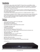
Introduction CATSwitchPro routes audio, video, IR and RS/232 signals from several different video sources out to multiple displays (projectors, monitors, etc.) and speakers via inexpensive Cat5/6 UTP cable. It supports pass-through IR and RS-232 signals for remote control of devices such as displays and switches.
Ordering Information Part Number Description CSW08X08S CAT5 Matrix audio/video 8x8 matrix with RS232 control. Includes: [CSW08X08 (SM-CSW) and (CCPWR06US) or (CCPWR06EU] CSW16X08S CAT5 Matrix audio/video 16x8 matrix with RS232 control. Includes: [CSW16X08 (SM-CSW) and (CCPWR06US) or (CCPWR06EU] CSW16X16S CAT5 Matrix audio/video 16x16 matrix with RS232 control. Includes: [CSW16X16 (SM-CSW) and (CCPWR06US) or (CCPWR06EU] CSWP08X08S CAT5 Matrix audio/video/IR and R232 8x8 matrix with RS232 control.
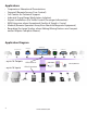
Applications • • • • • • • • Corporate or Educational Presentations Financial (Remote Servers/User Control) Call Centers for Technical Support Industrial (Long-Range Workstation Isolation) Airport Installations (Air Traffic Control/Passenger Information) KVM Extension where Exceptional Quality of Signal is Crucial Medical (Remote Operation Away from Sensitive/Magnetic Equipment) Recording (for Large Studios where Editing/Mixing Stations are Compact and/or Require Complete Silence) Application Diagram HDTV
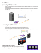
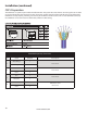
Installation Connecting XTAV transmitter Connecting The Transmitter 1. Connect the output of the computer video card to the video input of the transmitter using the included male to male video cable. 2. Connecttheoutputofthecomputeraudiocardtothe audio input of the transmitter using 3.5mm audio male to male audio cable. 3. Connectexternalspeakerstothetransmitter’saudio out (Standard 3.5mm stereo miniplug). 4. In the back of the unit connect the CAT5 cable that will connect to the receiver (XTAV-RX).
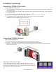
Installation (continued) Connecting XTWALL Transmitter Connecting The Transmitter 1. Connect the output of the computer video card to the video input of the transmitter using the included male to male video cable. 2. Connect the output of the computer audio card to the audio input of the transmitter using 3.5mm audio male to male audio cable. 3. Connect local monitor to the VGA out of the transmitter. 4. Connect external speakers to the transmitter’s audio out (Standard 3.5mm stereo miniplug). 5.
Installation (continued) Connecting the XTPro transmitter Connecting The Transmitter 1. Connect the output of the computer video card to the video input of the transmitter using the included male to male video cable. 2. Connect the output of the computer audio card to the audio input of the transmitter using 3.5mm audio male to male audio cable. 3. Connect local monitor to the VGA out of the transmitter. 4. Connect external speakers to the transmitter’s audio out (Standard 3.5mm stereo miniplug). 5.
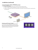
ower Supply Installation (continued) emote Control Connecting the XTPro-XTREEM receiver PS-5VDC2A RMT-2 Connecting The Receiver 1. Connect CAT5 cable (coming from the transmitter) to the back of the receiver. 2. Connect a display monitor to the VGA out connectors on the front of the receiver. 3. Connect a set of external speakers to the audio output connections on the front of the unit. (Standard 3.
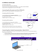
Installation (continued) Connecting the matrix Now you are ready to connect the CATSwitch, Connect all the cat5 coming from the transmitters to the inputs of the CATSwitch Connect all the cat5 going to the receivers to the output Connecting the the main unit, the CATSwitch Make sure the unit is powered off before connecting all the cables Connecting all the Transmitters 1 Locate the RJ45 jacks on the back of the CATSwitch, 2 Connect the CAT5 cable to the RJ45 and mark each cable with the number of the tr
Installation (continued) CAT5 Preparation The CATSwitch is a point to point video extender/switcher. The system does not allow to connecting the Cat5 via hubs or any kind of switches that the point to point connection need be maintained. The 16 RJ45 ports on the front of the CATSwitch are output ports, providing connectivity to the XTPro or XT-AV receiver. This is a standard RJ45 connector, the CATSwitch can be connected via either CAT5, CAT5e or CAT6 cabling.
Software Operation Find the Installation CD that came with your CATSWITCH unit. This CD has the SmartControlPro software that you will need in order to control the unit using a computer. Insert the CD into your CD-ROM. On the CD you should see: • SmartControl Pro Installer.exe • SmartControl Pro Help File • CATSWITCH Manual in PDF format Double click SmartControlPro.exe in order to initiate software installation. Click Install. After installation has completed, click CLOSE.
Software Operation (continued) Inputs/Outputs: Com Port: Enter the number of Inputs/Outputs your CATSWITCH has. For now we will assume that there are 16 inputs and 16 outputs. Select the appropriate com port that your computer is using to access the router. Router Time out: By default this is 0 meaning the computer acknowledges commands almost instantly. Sometimes a computer takes longer to respond. This setting should be left at 0.
Software Operation (continued) The Main Routing Window enables you to control the router(s) connections by means of the CATSWITCH panel, the button panel, or with pre-recorded routes called macros. CATSWITCH Panel: This is probably the simplest way to route the connections. Simply click on the cross point itself. The input on the left will then be routed to the output above. Note: Inputs can be routed to several different outputs, but each output can only have a single input at any one time.
Software Operation (continued) Macros: This section of the window is used to save and play back macros. Macros store a set sequence of routes. To record a macro: 1. Click on the Record button (last button shown above). A blinking “recording” message below this button will be displayed to indicate that all routes are being recorded. 2. Select the desired cross points. (See CATSWITCH Routing for details on making these routes.) There is no limit on the number of routes you may record. 3.
Software Operation (continued) Controlling with IR Switching Ports with Remote Control You have the option of controlling the CATSWITCH via Remote Control. The remote is used to control the CATSWITCH. The SM-EYE must be connected to the CATSWITCH ( this is an optional connector not always available in all boxes) in order to interface the remote control with the matrix.
Controlling the CATSwitch with the SMTCP module The SMTCP-2 is an RS-232 control module that allows most SmartAVI switching matrixes to be controlled remotely via HTTP or TELNET. Manage the switching functions of your matrix with ease from anywhere in the world. With the SMTCP-2 you can save up to 10 preset input/output configurations for easy access. TELNET access provides transparent command control of your matrix, perfect for use with automated third-party control software.
Controlling the CATSwitch with the SMTCP module (continued) Connecting to the SMTCP-2 for the first time The first time you connect the SMTCP-2, you will need to perform the following steps to set the initial configuration. This includes establishing an HTTP connection and manually setting the IP address for the SMTCP-2. 1. Power off all devices. 2. Use a female to male Straight-Through RS-232 (Serial) cable to connect the SMTCP-2 to the computer. 3.
Controlling the CATSwitch with the SMTCP module (continued) 8. Open a web browser and navigate to the IP address that is indicated. You will be prompted to enter a username and password. 9. The default login (case sensitive) is as follows: User ID: Admin Password: Pass 10. Once connected to the SMTCP-2, you will see the following menu of options: 1. 2. 3. 4. 5.
Controlling the CATSwitch with the SMTCP module (continued) Controlling the SMTCP-2 via HTTP Once you have completed the Initial Setup for the SMTCP-2, you can now begin configuring it for your matrix. The following details the individual menu options in the web interface: Matrix Menu The matrix menu allows you to set the crosspoints for the matrix. Crosspoints are used to route signals from the individual inputs to individual outputs.
Controlling the CATSwitch with the SMTCP module (continued) Device Config Menu The device configuration menu allows you to select the type of matrix you are using, specify the dimensions of the matrix, and assign names to the inputs, outputs and presets, reset the names and reset the system to factory defaults. To begin, set the type of device you are using from the drop-down menu labeled Device Type and specify the Matrix Dimensions.
Controlling the CATSwitch with the SMTCP module (continued) User Administration Menu The User Administration menu allows you to change the user name and password for the SMTCP-2. The default user name for the SMTCP-2 is Admin and the password is Pass. Once you modify the login information, press the Submit button to make the changes. Controlling the SMTCP-2 via TELNET Commands may be sent transparently to the matrix via a TELNET connection to the SMTCP-2.
Controlling the CATSwitch with the SMTCP module (continued) Connecting to the SMTCP-2 for the first time WITHOUT DHCP The first time you connect the SMTCP-2, you will need to perform the following steps to set the initial configuration. This includes establishing an HTTP connection and manually setting the IP address for the SMTCP-2. 1. Power off all devices. 2. Use a female to male Straight-Through RS-232 (Serial) cable to connect the SMTCP-2 to the computer. 3.
Technical Information XTAV SPECIFICATIONS XTPRO SPECIFICATIONS Receiver with local monitor, Audio and IR/RS-232 support Receiver with Video and Audio support VGA Data Format RGBHV, RGsB, YUV, Y/C, CVBS Resolution Up to 1900 x 1200 VGA, SVGA, XGA, SXGA Connector type HD 15 socket Format RGBHV, RGsB, YUV, Y/C, CVBS Resolution Up to 1900 x 1200 VGA, SVGA, XGA, SXGA Connector Type HD 15 socket VGA Data Audio Audio Signal Type Stereo unbalanced Signal Type Stereo unbalanced Connector 3.
Technical Information (continued) XTProWALL VGA Data Fromat RGBHV, RGsB, YUV, Y/C, CVBS Resolution Up to 1900 x 1200, VGA, SVGA, XGA, SXGA) Connector Type HD 15 socket Audio Signal Type Connector RS232 Stero unbalanced 3.5 mm jack socket DB9M TXD, RXD, Gnd. 9600 bps Power 24 Requirements 5VDC@.5A Connector 2.1mm DC jack (center +ve) Physical Dimensions Weight Face plate is 4.5” x 4.5 0.5 lbs www.smartavi.
RS-232 Specifications How to properly create an RS-232 connection between a PC and most SmartAVI RS-232 compliant devices Establish a connection to your RS-232 compliant device: 1. 2. 3. Connect a straight through male to female RS-232 cable (shown on right) to the RS-232 connector on the PC. Connect the other end of the cable to the RS-232 compliant device. Power on the device. Male to Female Straight Cable (not provided) Setting up the Terminal application: 1. 2. 3. 4. Open Hyperterminal on the PC.
RS-232 Specifications (continued) How to properly test an RS-232 connection between a PC and most SmartAVI RS-232 compliant devices After you have established a connection to your device use the following commands:
RS-232 Specifications (continued) How to properly test an RS-232 connection between a PC and most SmartAVI RS-232 compliant devices RS-232 Commands continued:
RS-232 Specifications (continued) How to properly test an RS-232 connection between a PC and most SmartAVI RS-232 compliant devices The following are example commands for the first 8 inputs and 8 outputs. The hexadecimal values of the commands are also listed.
RS-232 Specifications (continued) How to properly test an RS-232 connection between a PC and most SmartAVI RS-232 compliant devices input_1_output_6 / / F 0 0 M 0 6 I 0 1 input_2_output_6 / / F 0 0 M 0 6 I 0 2 input_3_output_6 / / F 0 0 M 0 6 I 0 3 input_4_output_6 / / F 0 0 M 0 6 I 0 4 input_5_output_6 / / F 0 0 M 0 6 I 0 5 input_6_output_6 / / F 0 0 M 0 6 I 0 6 input_7_output_6 / / F 0 0 M 0 6 I 0 7 input_8_output_6 / / F 0 0 M 0
RS-232 SPECIFICATION How to properly test an RS-232 connection between a PC and most SmartAVI RS-232 compliant devices 30 www.smartavi.
Limited Warranty Statement A. Extent of limited warranty 1. SmartAVI Technologies, Inc. warrants to the end-user customers that the SmartAVI product specified above will be free from defects in materials and workmanship for the duration of 1 year, which duration begins on the date of purchase by the customer. Customer is responsible for maintaining proof of date of purchase. 2.
© Copyright 2012 Smart-AVI, All Rights Reserved NOTICE The information contained in this document is subject to change without notice. Smart-AVI makes no warranty of any kind with regard to this material, including but not limited to, implied warranties of merchantability and fitness for any particular purpose. Smart-AVI will not be liable for errors contained herein or for incidental or consequential damages in connection with the furnishing, performance or use of this material.