A.C. MODULAR GENERATOR SYSTEM OWNERS MANUAL MODEL#: ER-6.
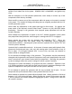
Smart Power® Systems A. C. MODULAR GENERATOR SYSTEM Page 1 of 52 Table of Contents Section Page Disclaimer .......................................................................................................................... 5 Description of Product...................................................................................................... 6 System Specifications ...................................................................................................... 9 Pre-Installation Guide .
Smart Power® Systems A. C. MODULAR GENERATOR SYSTEM Page 2 of 52 WARNING: Do not install or operate the A.C. modular generator system without reading this entire manual. The A.C. modular generator system will generate enough voltage to produce a fatal electrical shock. Do not perform any wiring installations or modifications while the system is operating. Never touch any live connections while the system is operating. Never operate the system with the generator wiring enclosure open.
Smart Power® Systems A. C. MODULAR GENERATOR SYSTEM Page 3 of 52 Never operate the system with leaks of any type. Clean up any hydraulic fluid that is spilled or has leaked out of the system. Hydraulic fluid is combustible, and ignition may occur. With the exception of oil filter periodic replacement, never modify or remove any of the components within the tray assembly. Never modify or remove any of the components within the pump or the controls mounted to the pump.
Smart Power® Systems A. C. MODULAR GENERATOR SYSTEM Page 4 of 52 Operating the A.C. modular generator system in the presence of flammable vapors may result in an explosion. Use only hoses that meet or exceed the minimum requirements specified in this manual. A ruptured hose can cause personal injury and/or damage to the generator system. Do not operate the system under electrical load with air in the hydraulic fluid (the system will make a growling sound).
Smart Power® Systems A. C.
Smart Power® Systems A. C. MODULAR GENERATOR SYSTEM Page 6 of 52 Description of Product Hydraulic Generator Applications: This heavy-duty electronically controlled generator system has been designed to meet the most demanding mobile applications. It provides 120/240 volt AC @ 60 Hz from no-load to full load, handling electrical loads of 6200, 8000 and 10000 watts, depending on model. How our System works: A generator driven by a hydraulic motor delivers the electrical power.
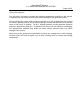
Smart Power® Systems A. C. MODULAR GENERATOR SYSTEM Page 7 of 52 BOOST BLOCK COOLER VENTURI BOOST x RESERVOIR y FILTER CHECK VALVE MOTOR BP REG IN PROPORTIONAL VALVE PUMP CASE DRAIN CASE DRAIN Hydraulic schematic for ER-6.
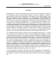
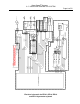
SYSTEM CONTROLLER P/N 8505028 (ER-6.2, ER-8, ER-10, ER-110) Electrical schematic for ER-6.2, ER-8, ER-10 and ER-110 generator systems RED/WHT PURP/WHT ORG/WHT BLU/WHT WHT/BLU WHT/RED BLK/YELL YELLOW GRN/WHT BLK/WHT YELLOW PURP GENERATOR OUTPUT GENERATOR OUTPUT GENERATOR OUTPUT RED WHT BLK BLK ORG RED 3 4 4 PURP/YELL YELL BLU PINK BLK GRN CONN 2 2 2 1 3 1 VEHICLE GND 2 1 4 3 2 1 CHASSIS GRN/WHT BLK/WHT PURP YELLOW 4 3 2 1 CURRENT TRANS.
Smart Power® Systems A. C. MODULAR GENERATOR SYSTEM Page 9 of 52 Figure 2 System Specifications MODEL OF GENERATOR Generator Type ER-6.
Smart Power® Systems A. C. MODULAR GENERATOR SYSTEM Page 10 of 52 Table 1 MODEL OF GENERATOR Oil Cooler Dimensions (Core) ER-6.2, ER-8 ER-10, ER-110 2.25”D x 12.5” W x 10.3” H 2.25”D x 22.
Smart Power® Systems A. C. MODULAR GENERATOR SYSTEM Page 11 of 52 Pre-Installation Guide Pre-Installation Check List 1. Verify that the Power Take Off (PTO) and the pump rotations match. To identify the pump rotation, check the pump part number found on the metal tag attached to side of the pump. A right hand rotating pump (the standard pump offered by Smart Power® Systems), will have the letter “R” in its part number. Example: A10VO (45 or 60) DFR-1/52 R PUC.
Smart Power® Systems A. C. MODULAR GENERATOR SYSTEM Page 12 of 52 3. Verify the combined weight of the pump and hoses filled with hydraulic fluid do not exceed the PTO manufacturer’s weight restriction. If the pump weight does exceed this restriction, the installer has two options: A) a bracket to support the pump can be implemented, or B) the pump can be mounted to the vehicle chassis, connected to the PTO with a drive shaft. 4. Verify that the pump shaft will mount to the PTO.
Smart Power® Systems A. C. MODULAR GENERATOR SYSTEM Page 13 of 52 WARNING: Do not install hose ends until proper hose length has been determined. Never install a hose in a location where it will rub against another surface or abrasion member. Do not position hoses with tight bend radii. Consult the hose manufacturer’s installation guidelines. Tight bends may kink and cause serious damage to the system and will void the system’s warranty.
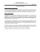
Smart Power® Systems A. C. MODULAR GENERATOR SYSTEM Page 14 of 52 12" MINIMUM OBSTRUCTION FREE CLEARANCE OIL FILTER ACCESS PANEL Front view of ER-6.2, ER-8, ER-10 and ER-110 tray assemblies showing minimum clearance for proper ventilation Figure 3 6" MINIMUM OBSTRUCTION FREE CLEARANCE 1" MAXIMUM SETBACK FROM FRONT OF COMPARTMENT Side view of ER-6.
Smart Power® Systems A. C. MODULAR GENERATOR SYSTEM Page 15 of 52 WARNING: Do not mount the hydraulic pump or tray assembly in any location that is not well ventilated. External heat sources elevating the hydraulic fluid and/or the generator temperature will result in premature wear and degraded system performance and void the system’s warranty. 7. The tray assembly must be mounted in a position that is higher than the pump.
Smart Power® Systems A. C. MODULAR GENERATOR SYSTEM Page 16 of 52 Installation Guide 1. Mount the pump securely to the Power Take-Off (PTO). This may require attaching a mounting bracket to the PTO housing prior to mounting the pump. WARNING: Always mount the hydraulic pump in a position with the pump controls up.
Smart Power® Systems A. C. MODULAR GENERATOR SYSTEM Page 17 of 52 3. Mount the tray assembly as high as possible within the structure of the vehicle. The ideal location for the generator is at the top of the truck in the dunnage area. The manufacturer must also take sufficient precautions to ensure that the generator is not mounted in the path of the deck gun/water cannon. 4. Mount the hydraulic generator tray securely to vehicle.
Smart Power® Systems A. C. MODULAR GENERATOR SYSTEM Page 18 of 52 3.375 1.688 .208 CLEARANCE HOLE FOR #10 SCREW 4 PL. 2.000 1.688 3.375 Hole pattern for Command & Control Center Figure 8 6. Flush the hoses with fresh hydraulic fluid (Dexron III). Install hoses and tighten hose ends, using the Hose Installation Guidelines. See Figure 27 and Figure 31 for connection locations WARNING: Never operate the system with the pump case drain plugged. Damage to the pump seals will result.
Smart Power® Systems A. C. MODULAR GENERATOR SYSTEM Page 19 of 52 Use caution when tightening the hose ends to prevent the hose from becoming twisted. Never install a 90° fitting at the pump outlet or inlet. Never use an inlet line fitting less than 1”. Never install a hose tightly between connections. Leave length for the hoses to expand. Do not form loops in the hose that may collect air or cause kinking. Run hose as straight as possible (but not taut) between connections.
Smart Power® Systems A. C. MODULAR GENERATOR SYSTEM Page 20 of 52 ALTERNATE CONFIGURATION: 120 VAC only: If the application requires 120 VAC only, the generator terminal strip should be configured as depicted below. This method ensures balanced loading of the generator, fully optimizing the system’s capabilities. Make the following wire connections at the terminal strip: a) place one jumper between wire 1 and wire 3. b) place the second jumper between wire 2 and wire 4.
Smart Power® Systems A. C. MODULAR GENERATOR SYSTEM Page 21 of 52 the system’s warranty. Replacement breakers must be obtained from Smart Power® Systems approved sources only. Do not perform any wiring installations or modifications while the system is operating. The A.C. modular generator system will generate enough voltage to produce a fatal shock. Never touch any live connections while the system is operating. Never operate the system with the generator cover removed. 8.
Smart Power® Systems A. C. MODULAR GENERATOR SYSTEM Page 22 of 52 Note: The generator is shipped from the factory with the purge option enabled. The system controller has been designed to provide a purge option. With this option applied, the generator will turn at a reduced speed to minimize wear to the system’s hydraulic components while purging air from the system. Once enabled, the purge option will remain set until automatically reset by the system controller.
Smart Power® Systems A. C. MODULAR GENERATOR SYSTEM Page 23 of 52 Enabling System Purge Option The purge option can also be set by performing the following steps: Step 5: Press On/Off until y appears. Step 3: Hold Mode until Amps Line 1 Blinks 88. Release switch so 0Pt appears. Step 4: Press mode to make PvrG appear. Figure 10 1. If the Command & Control Center is dark, press the Mode switch to put the display into Normal mode. 2. If the Display looks like Figure 11, The purge option is enabled. 3.
Smart Power® Systems A. C. MODULAR GENERATOR SYSTEM Page 24 of 52 g. Check for hydraulic fluid leaks, all hose connections must be tight. Monitor the hydraulic fluid level, adding fluid as needed to keep the level in the sight gauge full. h. After 10 minutes, the system controller will automatically switch the generator to “0N”. Check to see that the generator is turning (The frequency display should indicate 0n). If it is not, press the On/Off switch on the Command & Control Center to start the generator.
Smart Power® Systems A. C. MODULAR GENERATOR SYSTEM Page 25 of 52 Step b: Hold Mode until Amps Line 1 Blinks 88. Release switch so 0Pt and AStr appear. Step c: Press On/Off until the desired value appears Figure 12 Enabling Auto-Start Option a. If the Command & Control Center is dark, press the Mode switch to put the Command & Control Center into Normal mode. b. Press and hold the Mode switch until the Amps Line 1 field begins blinking 88 (more than 10 seconds). Release the switch so 0Pt and AStr appear.
Smart Power® Systems A. C. MODULAR GENERATOR SYSTEM Page 26 of 52 Operation 1. The Command & Control Center will show the generator’s output voltage, frequency, current, and system run time whenever the Command & Control Center is in the Normal mode. To access Normal mode, press the Mode switch repeatedly until the correct information is displayed (reference Figure 13). Example of Command & Control Center in normal mode Figure 13 2.
Smart Power® Systems A. C. MODULAR GENERATOR SYSTEM Page 27 of 52 Normally, the status lights will be off. When a switch is pressed, the corresponding light will be illuminated. When a status light is flashing, the corresponding switch is calibrating, and the switch should not be pressed. The system controller will ignore the switch while it is calibrating. 4.
Smart Power® Systems A. C. MODULAR GENERATOR SYSTEM Page 28 of 52 Displayed Oil Temperature in degrees Fahrenheit Example of oil temperature display Figure 16 b. When the Command & Control Center is in Normal mode, pressing the Mode switch twice will cause the amount of time since the oil filter was last changed to be displayed (reference Figure 17): Time Since last Oil Filter Change in Hours. Example of oil filter run time display Figure 17 c.
Smart Power® Systems A. C. MODULAR GENERATOR SYSTEM Page 29 of 52 The Er indicates the system controller is configured to operate an ER-series Generator The system controller is configured to operate a generator whose maximum output is this number (in kW). Example of configuration display Figure 18 d. If there are no active faults, pressing the Mode switch once more will return the Command & Control Center to its normal mode.
Smart Power® Systems A. C. MODULAR GENERATOR SYSTEM Page 30 of 52 a. From the Normal mode display, press Mode, as if you wanted to display the oil temperature. The screen shown in Figure 19 will be displayed instead, asking if you want to “Run hot.” This screen will also be displayed if you attempt to start the generator with the condition present. b. Note the y and n labels below the Mode and On/Off switches.
Smart Power® Systems A. C. MODULAR GENERATOR SYSTEM Page 31 of 52 Step a: Press Mode to cause rvn and the y and n labels to appear. Step b: Press On/Off to answer “yes” and make the next screen appear. Example of Command & Control Center in low oil fault override Figure 21 a. From the Normal mode display, press Mode, as if you wanted to display the oil temperature. The screen shown in Figure 21 will be displayed instead, asking if you want to “Run [with the] Oil Lo[w].
Smart Power® Systems A. C. MODULAR GENERATOR SYSTEM Page 32 of 52 Special Operating Instructions Cold Weather Procedure: It is strongly recommended that the generator PTO be engaged prior to leaving a heated garage or fire station in cold weather. The system will generate enough heat to keep its hydraulic fluid viscosity low enough for proper operation, in all but the most extremes of low ambient air temperatures.
Smart Power® Systems A. C. MODULAR GENERATOR SYSTEM Page 33 of 52 Maintenance Instructions WARNING: Do not perform maintenance while system is running. 1. Perform regular, periodic checks to verify: a. The cooler, the cooler fan and generator vents are not plugged by debris. b. There are no fluid leaks within the framework of the generator, along the hoses, or at the pump. c. The hoses are not cut, chaffed, bulged or kinked. d. That no electrical connections are loose. e.
Smart Power® Systems A. C. MODULAR GENERATOR SYSTEM Page 34 of 52 Lubricate the oil filter gasket with Dexron III before installation to permit proper sealing of the filter. WARNING: Do not by-pass the filter or alter filtration plumbing in any way. Doing so will void the system’s warranty. 3. The system controller automatically records the time from the previous filter change.
Smart Power® Systems A. C. MODULAR GENERATOR SYSTEM Page 35 of 52 Step a: Press Mode until InF, 0IL, and FILt appear. Step b: Hold Mode switch down and press On/Off three times in a row to clear the fault. Procedure will also work in the Oil Filter Hours Information display Example of oil filter service warning display Figure 25 a. Press the Mode switch repeatedly until one of the screens shown in Figure 25 appears. b.
Smart Power® Systems A. C. MODULAR GENERATOR SYSTEM Page 36 of 52 Troubleshooting Guide Diagnostic: The Command & Control Center will display certain faults that can assist a service technician in trouble shooting a problem with the generator system. When these faults occur, the fault message will periodically flash on the Command & Control Center, interrupting the normal display. Reference Figure 26 for an example of an over-current fault.
Smart Power® Systems A. C. MODULAR GENERATOR SYSTEM Page 37 of 52 Diagnostic Faults: The following is a list of the diagnostic faults, with a brief explanation of each.
Smart Power® Systems A. C. MODULAR GENERATOR SYSTEM Page 38 of 52 Hydraulic Problems: 1. Cavitation: Cavitation is caused by trying to pump more fluid than is available at the pump inlet due to system restrictions. Pump cavitation sounds like “marbles” passing through the pump. Conditions frequently associated with cavitation are the following: a. Too many restrictive fittings such as elbows and reducers on the pump inlet hose. b. Tight bends or kinks in pump inlet hose and/or tubing. c.
Smart Power® Systems A. C. MODULAR GENERATOR SYSTEM Page 39 of 52 3. Differential Pressure: Differential pressure between the inlet pressure and the case pressure over 7 psig causes the piston shoes to lift off the swash plate. This occurs due to the excessive lower pressure created on the fill (down) stroke of the piston. When the swash plate begins its upstroke, with pump rotation, it comes back into contact with the piston shoe, creating chatter. NOTE: This is NOT NORMAL.
Smart Power® Systems A. C. MODULAR GENERATOR SYSTEM Page 40 of 52 a. b. c. d. e. Check the oil cooler fins for debris or damage. Clean and/or replace cooler. Verify that the generator load is not excessive. Verify that there is proper ventilation. Verify that the DC fan motor is operating properly. Verify that warm air from the fan outlet is not being re-circulated through the cooler. f. Check the hydraulic fluid to see if it is black or darkened. This indicates overheating or aging.
Smart Power® Systems A. C. MODULAR GENERATOR SYSTEM Page 41 of 52 d. The stator field may be shorted or open. With a flashlight, check the generator windings visible through the ventilation slots. If the windings appear burnt in any area, the generator must be replaced. If the windings are not burnt, disconnect wires 1, 2, 3, and 4 from the terminal strip located in the generator wiring enclosure and make resistance measurement.
Smart Power® Systems A. C. MODULAR GENERATOR SYSTEM Page 42 of 52 h. The pump is faulty. If no faults are found in steps a. through g., the problem is likely to be a non-functional pump. Contact Smart Power® Systems at (231) 832-5525 for further instructions. 2. Output voltage exceeds 260 volts or falls below 220 volts AC on a 240 volt line: a. Verify that the hydraulic system is not overheating by viewing the temperature as displayed by the Command & Control Center.
Smart Power® Systems A. C. MODULAR GENERATOR SYSTEM Page 43 of 52 PUMP DISP. CC SHAFT K=KEYED S=SPLINE D(STD) SHAFT ROTATION R=CW (STD), L=CCW MOTOR DISP. CC POWER OUTPUT KILOWATT S5 GENERATOR, ER-6.2/45cc, R, SPL PUMP GENERATOR, ER-6.2/45cc, R, KEY PUMP GENERATOR, ER-6.2/45cc, L, SPL PUMP GENERATOR, ER-6.
Smart Power® Systems A. C. MODULAR GENERATOR SYSTEM Page 44 of 52 Component Part Number Lists (Reference Figure 27 and Figure 28) ITEM NO. PARENT 1 2 GENEROIL ATOR COOLER 3 ASM, FAN 4 5 ASM, FILTER PR. SW., FAN CONT. 6 TRAY 7 8 9 FILTER HOUSING HYD. ELEMENT BOOST MOTOR 10 11 12 GAUGE, BREATHER OIL RES. FLUID PLUG LEVEL 13 14 15 ASM, PUMP ELEC. CONT. UNIT PROP. CONT.
Smart Power® Systems A. C. MODULAR GENERATOR SYSTEM Page 45 of 52 ER-6.
Smart Power® Systems A. C.
Smart Power® Systems A. C. MODULAR GENERATOR SYSTEM Page 47 of 52 Pump Adjustment WARNING: The SPS Electronic Controlled Generators have been pre-set at the factory to provide correct frequency and voltage, no pump adjustments are required. If it appears the pump need to be adjusted, contact SPS at (231) 832-5525 before proceeding. Damage to the generator from improper pump adjustments will void the system’s warranty.
Smart Power® Systems A. C. MODULAR GENERATOR SYSTEM Page 48 of 52 The Pump Set option can be accessed by performing the following steps: Step d: After selecting PSEt, Press On/Off until y appears. Step b: Hold Mode until Amps Line 1 Blinks 88. Release switch so 0Pt appears. Step c: Press mode twice to make PSEt appear. Enabling pump set option Figure 29 a. If the Command & Control Center is dark, press the Mode switch to put the Command & Control Center into Normal mode. b.
Smart Power® Systems A. C. MODULAR GENERATOR SYSTEM Page 49 of 52 2. Adjust pump compensator: a. Loosen and remove flow control cap. Reference Figure 31. b. Loosen the flow control pressure jam nut. c. While monitoring the generator’s output voltage, slowly rotate the flow control set screw with a 3mm hex wrench. Adjust the flow control until the generator’s output frequency is 65 Hz. d. While keeping the setscrew from rotating, with the hex wrench, re-tighten the jam nut. e.
Smart Power® Systems A. C. MODULAR GENERATOR SYSTEM Page 50 of 52 3. Disable the generator Pump Set option. After the pump has been properly adjusted, disable the Pump Set option by performing the following steps: Step c: After selecting PSEt, Press On/Off until n appears. Step a: Hold Mode until Amps Line 1 Blinks 88. Release switch so 0Pt appears. Step b: Press mode twice to make PSEt appear. Disabling pump set option Figure 32 a.
Smart Power® Systems A. C. MODULAR GENERATOR SYSTEM Page 51 of 52 Manufacturers Limited Warranty Smart Power® Systems Hydraulic Generator Coverage period Provided such goods are operated and maintained in accordance with SPS’s written instructions, SPS warrants the hydraulic generators manufactured or supplied by it will be free from defects in material and workmanship for a period of five (5) years or one thousand (1,000) hours, whichever comes first, from the date of delivery to the first purchaser.
Smart Power® Systems A. C. MODULAR GENERATOR SYSTEM 5. Page 52 of 52 The cost of airfreight or other extraordinary expenses for shipment of parts over and above premium surface transportation. Limitation SPS is not responsible for the repair of generators that is required because of normal wear, accident, misuse, abuse, improper installation, corrosion, lack of maintenance, unauthorized modifications, the use of add-on or modified parts, improper storage or negligence.