
User's Manual


www.smartradarsystem.com
RM68-01 User Manual 페이지 9
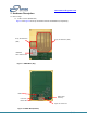
2.2 Connectors
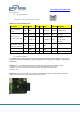
2.2.1 12-pin Connector
Connector - P/N : B12B-PUDSS-1(LF) (JST)
Table 2 12-Pin IO Connector Pin
Description
IN/OUT
Name
Num
Num
Name
IN/OUT
Description
Internal pulldown
(1kohm).
Input
SOP2
2
1
UART2_TX
Output
For MSS logger.
For flashing and
send the config data
Output
UART1_TX
4
3
UART2_RX
Input
Not used
Input
UART1_RX
6
5
AR_RESET_N
Input
Low Reset.
Internal pullup
(10kohm)
High Enable. Internal
pulldown (100kohm)
Input
PWR_EN
8
7
GND
GND
10
9
GND
5V/2A
Input
VDD_5V0
12
11
VDD_5V0
Input
5V/2A
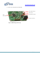
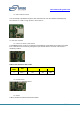
2.2.2 Power Connector
The RM68-NTA is powered by the 5-V power jack (4-A current limit), shown in Figure 7. As soon as
the power is provided, the RESET, PWR_OK and PWR LEDs should glow, indicating that the board is
powered on.
NOTE1: A 5-V, > 2.5-A supply brick with a 2.1-mm barrel jack (center positive) is not included. SRS
recommends using an external power supply that complies with applicable regional safety
standards, such as UL, CSA, VDE, CCC, PSE, and more. The length of the power cable
should be < 3 m.
NOTE2: After the 5-V power supply is provided to the RM68 debugger Board, it is recommended to press the
RESET switch (SW50) one time to ensure a reliable boot-up state.