
User's Manual


2
Wired Installation of the Keypad
NOTE: If you also plan to power the keypad with the gate opener’s battery and hard wire the com-
munication between the keypad and the gate opener, run two pairs of wires as described below. One
pair to hard-wire the keypad to the gate opener’s control board and the other pair to connect the
keypad to the gate opener’s battery.
Step 1: Turn the gate opener’s power switch OFF. Use 16 gauge (AWG) stranded, direct burial, low
voltage wire (part no. RB509) to connect the keypad to the opener control board. Run wire through
PVC pipe from the ground to keypad and from the ground to the opener control board to protect the
wire from lawn mowers or grazing animals.
Determine how the wire will enter the keypad (i.e. from the back through a hole drilled in the mount-
ing post or running the wire on the surface of the post). Remove the small rectangular knock-out on
the back of the keypad cover and pull the wire into the cover. Then mount the cover to the post using
the screws provided.
Keypad Description
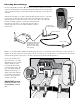
Installing Batteries
NOTE: Four (4) AA batteries (not included) are required to power the
keypad. If an external DC power supply such as the gate opener’s power
source is used, the AA batteries will act as a back up. Low voltage wire
from the external power source must be connected to the POWER IN
terminals on the keypad control board.
Step 1: Remove the two screws from the bottom of the keypad and
separate the keypad from its housing.
Step 2: Install four (4) AA batteries (not included).
"#$
%&'
()*
+,-
./0
134
567
89:
$ " - -
45"564
130(3".
$"--*/(
(3"/5&%
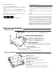
STATUS Light:
This led will blink once when any
key is pressed and provides visual
feedback during access code
programming.
GRANTED Light:
LED turns GREEN when access
permissiom is granted.
Keypad - Front
Battery Holder:
Use 4 AA batteries if hard-wired power supply
is not used. If external power source is used the
4 AA batteries will provide a back-up power
source.
2%,!9
/54054
!#$#
0/7%2).
o
*%4&5
o
o
o
o
3&4&5
+6.1&3
ID SET button:
This button is used only when there is another
pair of GTO wireless intercom units nearby
causing interference.
DIP Switches:
Match these switches to your remote
transmitter to program the keypad.
Relay output:
Used to connect the keypad to gate opener in
hard-wired applications.
Power Input:
Used to connect keypad to gate opener for
continuous power supply.
Keypad - Inside
Knock-out
Wireless Installation of the Keypad
NOTE: For wireless applications, the keypad must be in the line of sight of the gate opener receiver and the distance from the keypad
to the opener’s receiver should not exceed 50 ft. Always test the keypad range before permanently mounting it. Metal housing or ob-
jects could cause interference.
Step 1: Mount the keypad cover using the screws provided. Set the keypad
DIP switches to match your entry transmitter’s DIP switch settings.
NOTE: If you have not changed your opener’s
transmitter code from the factory setting, see
the “Setting Your Personal Transmitter Code”
section in the gate openers manual then set the
keypad DIP switches to match the new trans-
mitter DIP switch setting.
Step 2: Slide the keypad into the cover and secure with the small screws
provided.
1
2
ABC
3
DEF
4
GHI
5
JKL
6
MNO
7
PRS
8
TUV
9
WXY
0
CALL
STATUS
PROGRAM
CALLING
GRANTED
1 2 3 4 5 6 7 8 9
+
0
–
PROGRAM button:
Used to program access codes.
CALLING Light:
LED is RED when calling and turns
GREEN when call is answered.
RESET button:
Pressing this button for 2 seconds will
reprogram the keypad to factory settings. All
codes are deleted. Default master code is 1234.