
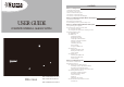
User's Manual

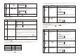


- LCD display flashes with “1”
- Enter the new 4-digit PIN
- Press to confirm
Keys
(1234/
4-digit PIN)
+
Description
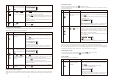
You must be in STANDBY
mode before programming
your new 4-digit PIN
Enter the default PIN “ 1 2
3 4 ” OR your new 4-digit
PIN for setting followed by
The Smart Panel will display the below image:
- Press then “1” to set the new PIN
- The Smart Panel will display the below image :
Note
1
2
3
4
SECTION 3 – USING THE
COMPLETE WIRELESS ALARM SYSTEM
mounting the tamperproof magnet
the mounting surface until firmly attached
enabled once the Smart Panel is switched to HOME, ALERT or ARM mode
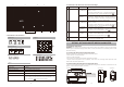
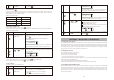
2.2 Powering up the Smart Panel controller
Note: The Smart Panel is supplied with a demonstration switch to show the LCD display panel working while
the unit is in its packaging. Before powering up the Smart Panel the wire for this switch must be removed as
described below (See Figs 1 & 2):
Fig. 2 ITSS-9000A
9V battery
Fig. 1 ITSS-9000A
Fig. 3 ITSS-9000A Fig. 4 ITSS-9000A
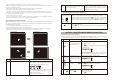
Step
1
Description Note
Insert 9V Alkaline backup battery One beep will sound and the backlight will blink
within 1 second (YellowėRedėGreenėYellow)
The Smart Panel will display the below image:
The Smart Panel will enter “STANDBY” mode after
the automatic self-checking is complete. Then will
appear on the LCD screen.
Enter the default 4-digit PIN “1234”
2 Battery voltage low level
Plug in AC adapter to the DC socket in the
back of the Smart Panel
The main power supply (with AC adaptor) must be
plugged in at all times, with the 9V battery
functioning as back-up power supply only, when the
main power supply is interrupted
Battery icon shows when the AC power supply is unplugged or interrupted.
9V battery functions as BACK-UP only and the symbol means LOW BATTERY.
The LCD backlight flashes YELLOW for 30 seconds and will blink until the new
battery is replaced or the main power supply (with AC adaptor) is plugged in.
When the AC adaptor to the Smart Panel is connected to a wall socket, the AC
symbol will appear.
The backlight will be ‘ON’ for 10 seconds while the AC adapter connects to the
power supply.
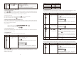
2.3 Understanding the battery and AC adaptor icon
Battery icon shows
power status below:
Full -
High -
Middle -
Low -
AC Adaptor icon
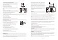
3.1 Programming your new 4-digit PIN
The Wire-free Home Protection Smart Panel is supplied with a default PIN of “1234”. This can be changed to
your own personalised PIN, or your own personalised PIN can be changed, as follows:
(1234/
4-digit PIN)
+
Press followed by
*To make sure you are in STANDBY mode:
- Enter the default PIN “ 1 2 3 4 ”
- Press
- The Smart Panel will display the image below when you are
in STANDBY mode:
(One beep indicates that you entered a valid PIN, three
beeps indicate that an invalid operation was performed).
New 4-digit
PIN +
Enter the new 4-digit PIN
followed by
- 5 -- 4 -