
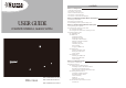
User's Manual

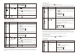


A. Powering up the the Door/Window Sensor
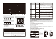
Remove the battery cover; insert new batteries noting the polarity
as shown in the diagram below and replace the cover. (Rees 2 x
AAA batteries not included)
Low battery indication: If the batteries need to be replaced, the RED
LED on the transmitter will flash slowly.
B. Installing the Door/Window Sensor
Mount the transmitter on a fixed surface such as a door or a window
frame.
Mount the magnet on a movable surface such as a door or a
window.
Ensure the >/< marks on the sides of the transmitter and magnet
match up as shown in the diagram.
The transmitter and the magnet must be no more than 5mm apart
C. Mounting with the double-sided adhesive pad
Ensure the mounting surface is clean.
Peel back one layer of the protective film and attach it to the transmitter.
Peel back the remaining layer of protective film and press the transmitter firmly in place against the mounting
surface until firmly attached.
Repeat to attach the magnet.
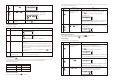
4.2.2 Installing the Motion Sensor
The Motion Sensor is designed to sense movement in a given area.
Note: It is best if pets are not allowed onto higher surfaces so that the sensors are not triggered unnecessarily
(no more than 1 metre high).
A. Powering up the Motion Sensor
Remove the battery cover, insert and connect a 9V ( 6LR61) battery
( not included ) as shown in diagram below and replace the cover.
Rees 1 x 9V ( 6LR61) battery( not included )
Low battery indication: If the batteries need to be replaced,
the RED LED will flash (not including entry / exit delay flashing).
B. Installing the Motion Sensor
First, determine the location of the Motion Sensor.
*Note: The Sensor should be placed:
- in the most vulnerable rooms or near key entry points.
- on a solid surface between 1.8m to 2.4mm (6ft to 8ft) from the floor.
- away from extreme temperature sources (radiators, ovens, stoves etc.)
- away from direct sunlight.
- indoors only and not behind partitions
- where better RF performance can be achieved (if necessary)
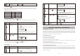
C. Sensor sensitivity
IMPORTANT! The Motion Sensor is designed with a built-in sleep timer to save battery power. If there is no
movement in front of the PIRs for 3 minutes, the PIRs will become ‘ready to signal’ and movement will now be
reported. The Motion Sensor will sleep for 3 minutes after reporting. Any movement detected in sleep time
will not be reported, please bear this in mind during system set up.
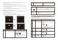
The sensitivity of the Motion Sensor is adjustable and can be changed by setting the connector, found in the
battery compartment, on either the “High”, “Middle” or “Low”
position. When the sensitivity is set to “Low”, more movement is
reed to trigger the sensor. It is recommended to set the
sensitivity to “Low” and perform a “Walk Test” (Described in part
D). If the walk test result is satisfactory, the sensitivity does not
ree further adjustment. If the walk test result shows the
sensitivity is too low, then the sensitivity can be set to “Middle” or
“High” as reed. It is recommended that a walk test be
conducted after each change in sensitivity setting.
Test Motion Sensor by pressing the test button inside the battery
compartment.
D. Walk test
After mounting the sensor at the desired location, it is important
to perform a walk test in order to determine if the sensor is
detecting the correct area.
The distance at which the sensor can detect motion can be adjusted by altering the angle of the sensor. To
reduce the detection range, simply move the sensor downward and move the sensor upward to maximize the
range.
Note: Enter into ALERT mode before you perform the walk test, so that the alarm is not triggered.
You should walk in the area that you would like the sensor to monitor. If movement is detected the red light
inside the unit will appear. If the red light does not appear, adjust the mounting angle accordingly. Perform
the walk test again after 3 minutes. Repeat this procedure until motion is detected. While carrying out the test,
there should be no movement in the detection area during the 3 minutes interval.
* Tips: The sensor should not face towards direct sunlight, be placed near heat or cold producing devices (i.e.
air conditioning, radiators, fans, ovens, heaters etc.) that may cause false triggers. Also perform the walk test
in areas which the sensor is not intended to cover, to ensure movement cannot be detected.
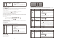
E. Mounting using screws
Hold the enclosed mounting template against the wall at the selected location and mark the points for
drilling.
Drill the holes and insert wall plugs.
Attach the bracket to the mounting surface with the screws provided.
Attach the Motion Sensor to the mounting bracket.
4.2.3 Introduction of Key Fob Remote Control
A. Introduction
The Complete Home Complete Wireless Alarm System Remote Control allows you to operate the systems
Smart Panel remotely, from inside or outside the property. Using the control the system can be armed or
disarmed and the siren can be activated instantly if reed (using the Panic function).
B. Operation
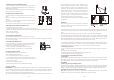
i. Powering up the Key Fob Remote Control
The Remote Control includes a 12V(MN27) alkaline battery. To activate, unscrew and remove the back of the
Remote Control, and carefully remove the clear plastic insulation tab from the battery. If the battery is dislodged,
replace it noting the correct polarity as shown inside the battery compartment. Replace the battery cover.
ii. Enrolling the Remote Control onto the Smart Panel
Note: Before being able to use the Key Fob Remote Control supplied with the system, or any additional
Remote Controls, they first need to be enrolled (added onto the system) as follows:
- 15 -- 14 -