SMART Board™ 600i3 and SBD600i3 Interactive Whiteboard System Configuration and User’s Guide
Product Registration If you register your SMART product, we’ll notify you of new features and software upgrades. Register online at www.smarttech.com/registration. Keep the following information available in case you need to contact SMART Technical Support.
Introduction Important Information Read This Section First Before you install and use your SMART Board™ 600i3 or SBD600i3 interactive whiteboard system, read and understand the safety warnings and precautions in this user’s guide, your projector user’s guide and the included warnings document. These safety warnings and precautions describe the safe and correct operation of your interactive whiteboard system and its accessories, helping you to prevent injuries and equipment damage.
ii | IN T RO D UC T IO N – IMP O RT AN T IN F O RMA TI O N Safety Warnings, Cautions and Important Information WARNINGS – GENERAL • Failure to follow the installation instructions included with your interactive whiteboard, or found in this guide, could result in personal injury or product damage. • Two people are required to safely mount the projector boom and the interactive whiteboard on a wall because the items might be too heavy for one person to maneuver onto their wall-mounting brackets.
ii i | IN T ROD UC T ION – IMP O RT AN T IN F O RMA TI O N WARNINGS – PROJECTOR • Refer to the safety warnings and precautions published in the UF55/UF55w projector manual. • Do not stare (or allow children to stare) directly into your projector’s beam of light. Instruct children not to look in the direction of this beam of light. Encourage users to keep their back to the projector when working at the interactive whiteboard.
iv | IN T RO D UC T IO N – IMP O RT AN T IN F O RMA TI O N • When replacing the projector lamp: – Turn the projector off and wait 30 minutes for the lamp to cool completely before removing the projector from the boom. – Do not remove any screws other than those specified in the lamp replacement instructions. – Wear protective eyewear while changing the lamp. Failure to do so can cause injury or loss of eyesight if the lamp shatters or bursts.
v | IN T RO D UC T IO N – IMP O RT AN T IN F O RMA TI O N CAUTIONS • Do not operate this unit immediately after moving it from a cold location to a warm location. When the unit is exposed to such a change in temperature, moisture could condense on the lens and crucial internal parts. Allow the system to reach room temperature before operation to prevent possible damage to the unit. • Do not place the unit in hot locations, such as near heating equipment.
vi | IN T RO D UC T IO N – IMP O RT AN T IN F O RMA TI O N IMPORTANT • Use the instructions that are in the UF55/UF55w projector boxes to install your system. Do not use the instructions in your SMART Board interactive whiteboard product box. • Do not set up or use your interactive whiteboard system in an area with excessive levels of dust, dirt, humidity or smoke. • Do not place your interactive whiteboard system near any appliance that generates a strong magnetic field.
Contents Important Information ..............................................................................................i Read This Section First ....................................................................................i Safety Warnings, Cautions and Important Information ....................................ii 1 About Your SMART Board 600i3 or SBD600i3 Interactive Whiteboard System ... 1 SMART Board 600i3 or SBD600i3 Interactive Whiteboard System Features 2 Interactive Whiteboard Features .
vi ii | CON T EN TS After Installing Your SMART Board 600i3 or SBD600i3 Interactive Whiteboard System..................................................................... 13 Adjusting Keystone Alignment ............................................................... 13 Focusing the Image................................................................................ 14 Performing an Image Alignment.............................................................
ix | CO N T EN TS Audio Control ......................................................................................... 42 Network Information ............................................................................... 43 System Information ................................................................................ 44 6 Troubleshooting Your SMART Board 600i3 or SBD600i3 Interactive Whiteboard System ...........................................................................
x | CO N T EN TS Replacing the Projector Lamp Module ................................................... 61 Replacing the Projector .......................................................................... 63 Resetting the Lamp Timer ...................................................................... 64 A Customer Support ............................................................................................... 65 Online Information and Support...................................................
Chapter 1 About Your SMART Board 600i3 or SBD600i3 Interactive Whiteboard System Your SMART Board 600i3 or SBD600i3 interactive whiteboard system combines the UF55/UF55w wall-mounted, short-throw projector system with a SMART Board 600 or SBD600 series interactive whiteboard. Refer to these topics to learn more about the features and accessories that you can use with your SMART Board 600i3 or SBD600i3 interactive whiteboard system.
2 | CH A P T E R 1 – A B O U T Y O U R S M A RT B O A R D 6 0 0I3 OR SBD 60 0I3 IN TE RAC T IVE W H I T EBO A R D S Y S T E M SMART Board 600i3 or SBD600i3 Interactive Whiteboard System Features Your SMART Board 600i3 or SBD600i3 interactive whiteboard system uses the UF55/UF55w short-throw, high-offset projector.
3 | CH A P T E R 1 – A B O U T Y O U R S M A RT B O A R D 6 0 0I3 OR SBD 60 0I3 IN TE RAC T IVE W H I T EBO A R D S Y S T E M Other features of your interactive whiteboard include: • A pen tray that automatically detects which tool you’ve selected when you pick up a pen or the eraser from the pen tray • Pen tray buttons that activate the on-screen keyboard, right-click and help functions • A durable hard-coated surface that’s tear-proof, optimized for projection, compatible with dry-erase markers, a
4 | CH A P T E R 1 – A B O U T Y O U R S M A RT B O A R D 6 0 0I3 OR SBD 60 0I3 IN TE RAC T IVE W H I T EBO A R D S Y S T E M • Protected cable routing through the projector housing and a cable cover to prevent tampering and clutter • A secure mounting and installation system that includes: – A projector padlock loop – Mounting hardware for solid masonry or framed wall installations – Templates and instructions for positioning the system in a safe manner ECP and Cable Your interactive whiteboard
5 | CH A P T E R 1 – A B O U T Y O U R S M A RT B O A R D 6 0 0I3 OR SBD 60 0I3 IN TE RAC T IVE W H I T EBO A R D S Y S T E M Standard Accessories The following accessories are included with your SMART Board 600i3 or SBD600i3 interactive whiteboard system. Remote Control The remote control enables you to control the system and set up your UF55/UF55w projector. Use the remote control to access menu options, system information and input selection options.
6 | CH A P T E R 1 – A B O U T Y O U R S M A RT B O A R D 6 0 0I3 OR SBD 60 0I3 IN TE RAC T IVE W H I T EBO A R D S Y S T E M Optional Accessories For more information about these optional accessories, contact your authorized SMART reseller. SMART Board Audio (SBA) USB Speakers Your interactive whiteboard system requires an audio system to deliver presentations with sound. The SBA system consists of a pair of 15-watt, stereo-amplified speakers with a two-port USB hub and a volume control knob.
7 | CH A P T E R 1 – A B O U T Y O U R S M A RT B O A R D 6 0 0I3 OR SBD 60 0I3 IN TE RAC T IVE W H I T EBO A R D S Y S T E M GoWire™ SMART Notebook Software Auto-launch Cable (USB-GW) The GoWire cable contains SMART Notebook software and launches it automatically on a guest computer, providing full access to all interactive whiteboard software tools without installing SMART Notebook.
8 | CH A P T E R 1 – A B O U T Y O U R S M A RT B O A R D 6 0 0I3 OR SBD 60 0I3 IN TE RAC T IVE W H I T EBO A R D S Y S T E M
Chapter 2 Installing Your SMART Board 600i3 or SBD600i3 Interactive Whiteboard System Consult the SMART Board 600i3 or SBD600i3 interactive whiteboard system installation documents that came with your product for instructions on how to install your product and use the mounting template and the ECP. IMPORTANT Use the instructions included in the UF55/UF55w projector boxes to install your system. Do not use the instructions in your SMART Board interactive whiteboard’s product box.
10 | CH A P T E R 2 – I NSTAL LI NG YOUR S MAR T BOAR D 60 0I3 OR SB D6 00I 3 I N T E R A C T I V E W H I T E B O A RD S Y S T E M Environmental Requirements Before installing your SMART Board 600i3 or SBD600i3 interactive whiteboard system, review the following environmental requirements. CAUTION • Do not operate this unit immediately after moving it from a cold location to a warm location.
11 | CH A P T E R 2 – I NSTAL LI NG YOUR S MAR T BOAR D 60 0I3 OR SB D6 00I 3 I N T E R A C T I V E W H I T E B O A RD S Y S T E M Environmental Requirement Parameter Operating temperature • 41°F to 95°F (5°C to 35°C) from 0' to 6000' (0 m to 1829 m) • 41°F to 86°F (5°C to 30°C) from 6000' to 9800' (1829 m to 2987 m) Storage temperature -40°F to 122°F (-40°C to 50°C) Humidity • 30 to 70% relative humidity, non-condensing • Humidity above 80% might cause slight wrinkling in the screen surface sheet.
12 | CH A P T E R 2 – I NSTAL LI NG YOUR S MAR T BOAR D 60 0I3 OR SB D6 00I 3 I N T E R A C T I V E W H I T E B O A RD S Y S T E M Before Installing Your SMART Board 600i3 or SBD600i3 Interactive Whiteboard System Choose a location for your SMART Board 600i3 or SBD600i3 interactive whiteboard system that’s far from bright light sources, such as windows or overhead lighting.
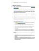
13 | CH A P T E R 2 – I NSTAL LI NG YOUR S MAR T BOAR D 60 0I3 OR SB D6 00I 3 I N T E R A C T I V E W H I T E B O A RD S Y S T E M After Installing Your SMART Board 600i3 or SBD600i3 Interactive Whiteboard System Adjusting Keystone Alignment Keystone errors occur when the projected image isn’t perpendicular to the screen. From the projector, the image path is shorter along the top. From the projector, the image path is shorter along the bottom.
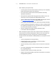
14 | CH A P T E R 2 – I NSTAL LI NG YOUR S MAR T BOAR D 60 0I3 OR SB D6 00I 3 I N T E R A C T I V E W H I T E B O A RD S Y S T E M The image appears shorter across the right side when the distance from the projector to the right side of the screen is shorter than the distance to the left side of the screen. The image appears shorter across the left side when the distance from the projector to the left side of the screen is shorter than the distance to the right side of the screen.
15 | CH A P T E R 2 – I NSTAL LI NG YOUR S MAR T BOAR D 60 0I3 OR SB D6 00I 3 I N T E R A C T I V E W H I T E B O A RD S Y S T E M Performing an Image Alignment Use this procedure to obtain a rectangular image that’s slightly smaller than your interactive whiteboard’s screen. NOTES To perform an initial image alignment • Project a computer image (set to the proper resolution) while performing the following steps.
16 To adjust the projector alignment | CH A P T E R 2 – I NSTAL LI NG YOUR S MAR T BOAR D 60 0I3 OR SB D6 00I 3 I N T E R A C T I V E W H I T E B O A RD S Y S T E M 1. If the bottom edge of the projected image is smaller than the top edge of the projected image, and the sides of the projected image slope inward toward the bottom of the projected image, tilt the projector down or raise the projector’s mounting boom to lower the image.
17 | CH A P T E R 2 – I NSTAL LI NG YOUR S MAR T BOAR D 60 0I3 OR SB D6 00I 3 I N T E R A C T I V E W H I T E B O A RD S Y S T E M 3. Adjust the projected image’s horizontal alignment by turning the projector left or right, until the top and bottom edges of the projected image are horizontal and parallel. NOTE Don’t pay attention to the position of the left and right edges relative to your interactive whiteboard during this step. 4.
18 | CH A P T E R 2 – I NSTAL LI NG YOUR S MAR T BOAR D 60 0I3 OR SB D6 00I 3 I N T E R A C T I V E W H I T E B O A RD S Y S T E M 6. Move the projector forward or backward on the boom to make the image larger or smaller. NOTE During this step, you may need to tilt or turn the projector slightly to keep the image square. 7. Focus the projector using the focus lever (located on the top of the projector). NOTE You may need to repeat all steps in smaller increments in order to fine-tune the image. 8.
19 | CH A P T E R 2 – I NSTAL LI NG YOUR S MAR T BOAR D 60 0I3 OR SB D6 00I 3 I N T E R A C T I V E W H I T E B O A RD S Y S T E M Securing the Pen Tray and Interactive Whiteboard Because your SMART Board interactive whiteboard’s pen tray is detachable, you might want to safeguard it—and your interactive whiteboard—by anchoring it with a security cable.
20 | CH A P T E R 2 – I NSTAL LI NG YOUR S MAR T BOAR D 60 0I3 OR SB D6 00I 3 I N T E R A C T I V E W H I T E B O A RD S Y S T E M Since you can remove the pen tray without tools, you might want to securely attach it to its brackets. To do this, insert two No. 8/M4 screws (not included) into the holes indicated in the following illustration. NOTE Older pen trays don’t have this feature.
Chapter 3 Connecting Your SMART Board 600i3 or SBD600i3 Interactive Whiteboard System Refer to these topics for software installation instructions, relevant precautions and methods for connecting new devices to your interactive whiteboard system. Installing SMART Software........................................................................... 22 Connecting the Cables to the UF55/UF55w Projector.................................. 23 Routing the Cables.......................................................
22 | CH A P T E R 3 – C O N N E C T I N G Y O U R S M A R T BOAR D 60 0I 3 OR S BD6 00 I3 I N T E R A C T I V E W H I T E B O A RD S Y S T E M Installing SMART Software When you connect a computer with SMART product drivers and SMART Notebook software to your system, you can control your computer from your interactive whiteboard’s screen, write in digital ink over your projected desktop or directly into any Ink Aware application, and then save your notes to a SMART Notebook file.
23 | CH A P T E R 3 – C O N N E C T I N G Y O U R S M A R T BOAR D 60 0I 3 OR S BD6 00 I3 I N T E R A C T I V E W H I T E B O A RD S Y S T E M Connecting the Cables to the UF55/UF55w Projector Refer to the following diagrams while you connect the cables to the projector.
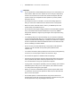
24 To connect the power, ECP and network cables to the projector | CH A P T E R 3 – C O N N E C T I N G Y O U R S M A R T BOAR D 60 0I 3 OR S BD6 00 I3 I N T E R A C T I V E W H I T E B O A RD S Y S T E M 1. Remove the projector’s cable cover. 2. Pass the cable through the boom, and then connect it to the power supply receptacle. Make sure that the power cable is in the far right position in the cable slot. Cable Slot Power Supply Receptacle 3. Pass the ECP cable through the boom.
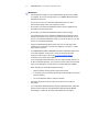
25 | CH A P T E R 3 – C O N N E C T I N G Y O U R S M A R T BOAR D 60 0I 3 OR S BD6 00 I3 I N T E R A C T I V E W H I T E B O A RD S Y S T E M 4. Connect the ECP cables to the projector by connecting each section separately. – Connect the S-Video and two Audio cables to the receptacles in section A. – Connect the Video and two Audio cables to the receptacles in section B. – Connect the Audio 2 and Computer 2 VGA cables to the receptacles in section C.
26 | CH A P T E R 3 – C O N N E C T I N G Y O U R S M A R T BOAR D 60 0I 3 OR S BD6 00 I3 I N T E R A C T I V E W H I T E B O A RD S Y S T E M 6. Pass the Audio, VGA and network cables (not included) through the boom, and then connect them to your projector. – Connect the Audio 1 and Computer 1 VGA from your external computer (section E). – Connect the RJ-45 network cable from your external LAN receptacle (section F). NOTES – These cables are for optional equipment.
27 | CH A P T E R 3 – C O N N E C T I N G Y O U R S M A R T BOAR D 60 0I 3 OR S BD6 00 I3 I N T E R A C T I V E W H I T E B O A RD S Y S T E M Connecting Your Guest Computer to the ECP’s Inputs IMPORTANT To connect your guest computer’s video or audio output to your ECP • Use the VGA connector on the ECP to connect your guest computer’s video output. If you do not have a guest computer, use the VGA connector on the ECP to connect your host computer’s video output.
28 | CH A P T E R 3 – C O N N E C T I N G Y O U R S M A R T BOAR D 60 0I 3 OR S BD6 00 I3 I N T E R A C T I V E W H I T E B O A RD S Y S T E M Connecting Peripheral Visual or Audio-Visual Devices To connect a DVD player, VCR, document camera, digital camera or other peripheral visual or audio-visual device to your SMART Board interactive whiteboard system, you must connect the device’s video and audio outputs to the ECP. You can connect up to three peripheral devices and a host computer at the same time.
Chapter 4 Using Your SMART Board 600i3 or SBD600i3 Interactive Whiteboard System This chapter describes the basic operation of your interactive whiteboard system, and also explains how to retrieve system information and access the projector’s image adjustment options. Turning the System On and Off and Selecting an Input ............................... 30 Using Your Interactive Whiteboard ............................................................... 30 Using Your UF55/UF55w Projector .....................
30 | CH A P T E R 4 – U S I NG Y O U R S M A R T B O A R D 6 00 I3 O R S B D 6 0 0 I 3 I NT E R A C T I V E W H I T E BO A R D S Y S T E M Turning the System On and Off and Selecting an Input Your ECP has a Power button and four Input Selection buttons. You can connect up to three peripheral devices and one host computer at the same time. You can add your own labels to the ECP buttons. The ECP’s Power button includes a cool down function that extends the lamp’s life span.
31 | CH A P T E R 4 – U S I NG Y O U R S M A R T B O A R D 6 00 I3 O R S B D 6 0 0 I 3 I NT E R A C T I V E W H I T E BO A R D S Y S T E M Using Your UF55/UF55w Projector The UF55/UF55w projector includes two LED indicators. Refer to the Power and Temperature status indicators on the projector’s underside to determine the projector status and to troubleshoot unexpected behavior.
32 | CH A P T E R 4 – U S I NG Y O U R S M A R T B O A R D 6 00 I3 O R S B D 6 0 0 I 3 I NT E R A C T I V E W H I T E BO A R D S Y S T E M Menu Heading Image Adjustment, cont’d. Settings Description H-position Adjusts the horizontal position of the projected image from 0 to 100 NOTE: Don’t adjust this option unless a certified SMART Technical Support Specialist advises you to. You can apply these settings only after all other changes to the boom are made. This option applies to VGA inputs only.
33 | CH A P T E R 4 – U S I NG Y O U R S M A R T B O A R D 6 00 I3 O R S B D 6 0 0 I 3 I NT E R A C T I V E W H I T E BO A R D S Y S T E M Menu Heading Settings Description Default Settings Auto Signal Detect Select On to scan until the first input signal is found, or select Off to maintain signal detection in one input connector. Lamp Reminder Select On or Off to show or hide the change lamp warning message when it appears.
34 | CH A P T E R 4 – U S I NG Y O U R S M A R T B O A R D 6 00 I3 O R S B D 6 0 0 I 3 I NT E R A C T I V E W H I T E BO A R D S Y S T E M Menu Heading Settings Description Subnet Mask Displays the subnet mask number in x.x.x.x format Gateway Displays the default gateway of the network to the projector in x.x.x.x format DNS Displays the DNS number in x.x.x.
Chapter 5 Remotely Managing Your SMART Board 600i3 or SBD600i3 Interactive Whiteboard System This chapter includes detailed instructions on how to set up your computer or room control system to manage your SMART Board 600i3 or SBD600i3 interactive whiteboard system settings. Connecting Your Room Control System to the ECP .................................... 36 Pin Configuration on the ECP RS-232 Connector.................................. 36 Serial Interface Settings .......................................
36 | CH A P T E R 5 – R E MO T E L Y M A N A G IN G Y O U R SMA RT B O ARD 6 00 I3 O R S B D 6 0 0 I 3 I NT E R A C T I V E W H I TE BO A R D S Y S T E M Connecting Your Room Control System to the ECP You can externally manage projector settings by connecting a computer or room control system to the serial interface (RS-232) on the ECP for the UF55/UF55w projector.
37 | CH A P T E R 5 – R E MO T E L Y M A N A G IN G Y O U R SMA RT B O ARD 6 00 I3 O R S B D 6 0 0 I 3 I NT E R A C T I V E W H I TE BO A R D S Y S T E M Setting Value Stop Bits 1 Flow Control None NOTES To configure your computer’s serial interface • All commands should be in ASCII format. Terminate all commands with a carriage return. • All responses from the ECP are terminated with a carriage return line feed combination followed by a command prompt.
38 | CH A P T E R 5 – R E MO T E L Y M A N A G IN G Y O U R SMA RT B O ARD 6 00 I3 O R S B D 6 0 0 I 3 I NT E R A C T I V E W H I TE BO A R D S Y S T E M UF55/UF55w Programming Commands Powerstate Controls The UF55/UF55w projector responds to commands only at certain power levels and times. There are four projector power states: • Idle • Powering (startup) • On (operating) • Cooling (idle) The embedded firmware program coordinates command sequencing and is capable of buffering up to 127 commands.
39 To allow the ECP to sequence commands To control the sequence programmatically | CH A P T E R 5 – R E MO T E L Y M A N A G IN G Y O U R SMA RT B O ARD 6 00 I3 O R S B D 6 0 0 I 3 I NT E R A C T I V E W H I TE BO A R D S Y S T E M 1. Type on, and then press ENTER. 2. Type set input=vga1, and then press ENTER.
40 | CH A P T E R 5 – R E MO T E L Y M A N A G IN G Y O U R SMA RT B O ARD 6 00 I3 O R S B D 6 0 0 I 3 I NT E R A C T I V E W H I TE BO A R D S Y S T E M Powerstate Control The Powerstate control enables the projector to turn on or off and switch between other related controls. Command Response Powered Off on powerstate=[powerstate] yes off [off option] powerstate=[powerstate] yes get powerstate powerstate=[powerstate] yes NOTE You must send the Off command twice.
41 | CH A P T E R 5 – R E MO T E L Y M A N A G IN G Y O U R SMA RT B O ARD 6 00 I3 O R S B D 6 0 0 I 3 I NT E R A C T I V E W H I TE BO A R D S Y S T E M Source Selection The Source Selection control enables you to switch between input sources. .
42 | CH A P T E R 5 – R E MO T E L Y M A N A G IN G Y O U R SMA RT B O ARD 6 00 I3 O R S B D 6 0 0 I 3 I NT E R A C T I V E W H I TE BO A R D S Y S T E M Field Possible Values Description current brightness 0 to 100 Indicates the current brightness target contrast +val If you specify a + or - before the value, the specified value is added or subtracted from the current value. If you indicate a specific numerical value, the contrast sets directly to the number.
43 | CH A P T E R 5 – R E MO T E L Y M A N A G IN G Y O U R SMA RT B O ARD 6 00 I3 O R S B D 6 0 0 I 3 I NT E R A C T I V E W H I TE BO A R D S Y S T E M Network Information The Network Information commands enables you to display various types of network information.
44 | CH A P T E R 5 – R E MO T E L Y M A N A G IN G Y O U R SMA RT B O ARD 6 00 I3 O R S B D 6 0 0 I 3 I NT E R A C T I V E W H I TE BO A R D S Y S T E M System Information The System Information commands enable you to display various types of system information.
Chapter 6 Troubleshooting Your SMART Board 600i3 or SBD600i3 Interactive Whiteboard System This chapter provides basic troubleshooting information for your SMART Board 600i3 or SBD600i3 interactive whiteboard system. For more complex issues or issues not covered in this section, contact your authorized SMART reseller or the SMART Technical Support website. System Warning Lights................................................................................. 46 ECP Ready Light and System Status.............
46 | CH A P T E R 6 – TR O U B L E S H O O T I N G Y O U R S M ART BOARD 60 0I 3 OR SBD 600 I3 I N T E R A C T I V E W H I T E B O A RD S Y S T E M System Warning Lights ECP Ready Light and System Status The ECP ready light is located on the ECP’s main power button. This button also functions as your status warning light. Ready Light Status Off The projector system isn’t receiving power. Check your power cord, RS-232 connector at the projector (located below the power cable) and power supply.
47 | CH A P T E R 6 – TR O U B L E S H O O T I N G Y O U R S M ART BOARD 60 0I 3 OR SBD 600 I3 I N T E R A C T I V E W H I T E B O A RD S Y S T E M Power LED (Green/Amber) Temperature LED (Red) Error (Temperature Exceeded) Off Flashing Red Error (Fan Failure) Off Solid Red Error (Color Wheel Failure) Off Solid Red Error (Lamp Failure) Solid Amber Flashing Red Message Errors Temperature Exceeded If the Temperature Exceeded indicator message appears and your projector turns off during use, o
48 | CH A P T E R 6 – TR O U B L E S H O O T I N G Y O U R S M ART BOARD 60 0I 3 OR SBD 600 I3 I N T E R A C T I V E W H I T E B O A RD S Y S T E M Color Wheel Failure If the Color Wheel Failure error message appears and your projector turns off during use, your projector has an internal problem. To resolve the color wheel failure error 1. Disconnect the power cord from the power outlet. 2. Reconnect the power cord. 3.
49 To resolve your unlit ready light issue | CH A P T E R 6 – TR O U B L E S H O O T I N G Y O U R S M ART BOARD 60 0I 3 OR SBD 600 I3 I N T E R A C T I V E W H I T E B O A RD S Y S T E M 1. Check the power source, and then make sure that all cables are connected. 2. Confirm that your projector is connected to an active power outlet. 3. Make sure that the pins on the connectors aren’t broken or bent. 4. Make sure that the Hide Display feature on the remote is disabled. 5.
50 | CH A P T E R 6 – TR O U B L E S H O O T I N G Y O U R S M ART BOARD 60 0I 3 OR SBD 600 I3 I N T E R A C T I V E W H I T E B O A RD S Y S T E M
Chapter 7 Maintaining Your SMART Board 600i3 or SBD600i3 Interactive Whiteboard System This chapter includes methods for preventing damage to and properly cleaning your SMART Board 600i3 or SBD600i3 interactive whiteboard system. Follow the additional instructions and recommendations in the SMART Board 600 and SBD600 Series Interactive Whiteboard Installation and User’s Guide (document 1414) to properly maintain your interactive whiteboard system. Preventing Damage to Your Interactive Whiteboard...........
52 | CH A P T E R 7 – MA INT AI NI NG YO UR S MAR T BOAR D 60 0i3 OR SBD 60 0I3 I N T E R A C T I V E W H I T E B O A RD S Y S T E M Preventing Damage to Your Interactive Whiteboard Although your SMART Board interactive whiteboard’s surface is very durable, take the following precautions to prevent damage to the interactive screen and other components. • Don’t use sharp or pointed objects, such as ballpoint pens or pointers, as writing tools.
53 | CH A P T E R 7 – MA INT AI NI NG YO UR S MAR T BOAR D 60 0i3 OR SBD 60 0I3 I N T E R A C T I V E W H I T E B O A RD S Y S T E M Removing Permanent Marker Ink Stains To remove marks made with a permanent marker, use a cleaner such as Sanford EXPO Dry Erase Board Doctor. Write directly over the permanent ink stain with the Board Doctor pen, allow the solution to dry completely, and then wipe clean.
54 | CH A P T E R 7 – MA INT AI NI NG YO UR S MAR T BOAR D 60 0i3 OR SBD 60 0I3 I N T E R A C T I V E W H I T E B O A RD S Y S T E M Cleaning the UF55/UF55w Projector WARNING Cleaning a boom-mounted projector may result in a fall and injury. CAUTION • Before you clean the UF55/UF55w projector, press the power button twice on the ECP or remote to put the system into Idle mode, and then allow the bulb to cool for 30 minutes.
55 | CH A P T E R 7 – MA INT AI NI NG YO UR S MAR T BOAR D 60 0i3 OR SBD 60 0I3 I N T E R A C T I V E W H I T E B O A RD S Y S T E M Transporting Your SMART Board 600i3 or SBD600i3 Interactive Whiteboard System Save your original SMART Board 600i3 or SBD600i3 interactive whiteboard system packaging so that it’s available if you need to transport your interactive whiteboard system. When required, repack it with as much of the original packaging as possible.
56 | CH A P T E R 7 – MA INT AI NI NG YO UR S MAR T BOAR D 60 0i3 OR SBD 60 0I3 I N T E R A C T I V E W H I T E B O A RD S Y S T E M
Chapter 8 Replacing Your UF55/ UF55w Projector Lamp This chapter has detailed instructions on how to replace your projector lamp. Replacing the Projector Lamp ...................................................................... 57 Removing the Projector from the Boom ................................................. 59 Replacing the Projector Lamp Module ................................................... 61 Replacing the Projector .........................................................................
58 | CH A P T E R 8 – R E P L A C I NG Y O U R U F 5 5 / U F 5 5 W P R O J E C T O R L A M P • If the lamp has shattered or burst: • • • – Call your authorized SMART reseller for instructions. Do not attempt to replace the lamp. – Do not touch the glass fragments because they might cause injury. – Leave and then ventilate the area where the lamp shattered or burst. – Wash your hands thoroughly if you have come in contact with lamp debris.
59 | CH A P T E R 8 – R E P L A C I NG Y O U R U F 5 5 / U F 5 5 W P R O J E C T O R L A M P Removing the Projector from the Boom Before you can replace the projector lamp, you must remove the projector from the boom. NOTE Ensure that you remove the projector’s plastic lens cover. WARNING Two people are required to remove and replace the projector. To remove the projector from the boom 1. Turn off the projector by pressing the remote control’s power button. 2.
60 | CH A P T E R 8 – R E P L A C I NG Y O U R U F 5 5 / U F 5 5 W P R O J E C T O R L A M P 5. If you use a projector padlock, make sure that you remove it from the locking loop. If you need access to the projector locking screw, loosen the wingnut and slide the projector all the way back, away from your interactive whiteboard’s screen, and then re-tighten the wingnut. 6. Remove the single screw on the bracket with a Phillips® No. 2 screwdriver. Place the screw in a safe place.
61 | CH A P T E R 8 – R E P L A C I NG Y O U R U F 5 5 / U F 5 5 W P R O J E C T O R L A M P Replacing the Projector Lamp Module After you remove the lamp from the boom, follow these instructions to replace the lamp. To remove and replace the lamp 1. Wait at least 30 minutes for the projector to completely cool down. 2. Pull up the outer lamp cover with your finger. 3. Remove the outer lamp cover and keep it in a safe place. 4. Loosen the two screws on the inner lamp module with a Phillips No.
62 | CH A P T E R 8 – R E P L A C I NG Y O U R U F 5 5 / U F 5 5 W P R O J E C T O R L A M P 5. Pull up on the lamp module’s handle, and then remove the lamp. IMPORTANT Recycle or dispose of the lamp module according to your local waste authority. 6. Remove the replacement lamp module’s packaging. CAUTION Do not touch any part of the lamp module except the housing. 7.
63 | CH A P T E R 8 – R E P L A C I NG Y O U R U F 5 5 / U F 5 5 W P R O J E C T O R L A M P Replacing the Projector WARNING Two people are required to replace the projector. To replace the projector on the boom 1. Put the projector back on the boom by aligning the hooks with the slots on the projector. CAUTION Hold the projector firmly when re-attaching it to the stationary boom. 2. Secure the projector to the plate with the screw that you retained after you removed the projector from the boom.
64 | CH A P T E R 8 – R E P L A C I NG Y O U R U F 5 5 / U F 5 5 W P R O J E C T O R L A M P 4. Connect all cables to the projector, and then attach the cable cover. 5. Replace the cover on the top of the boom. 6. Replace and tighten the screw until it’s secure, without applying pressure or weight to the projector boom. 7. Connect the power cord to the wall power outlet, and then wait for the projector to turn on completely. 8. If required, re-adjust the projected image. See page 15.
Appendix A Customer Support Online Information and Support Visit www.smarttech.com/support to view and download user’s guides, how-to and troubleshooting articles, software and more. Training Visit www.smarttech.com/trainingcenter for training materials and information about our training services. Technical Support If you experience difficulty with your SMART product, please contact your local reseller before contacting SMART Technical Support. Your local reseller can resolve most issues without delay.
66 | AP PENDI X A – C U S T O M E R S U P PO R T General Inquiries Address SMART Technologies 3636 Research Road NW Calgary, AB T2L 1Y1 CANADA Switchboard +1.403.245.0333 or Toll Free 1.888.42.SMART (U.S./Canada) Fax +1.403.228.2500 E-mail info@smarttech.com Warranty Product warranty is governed by the terms and conditions of SMART’s “Limited Equipment Warranty” that shipped with the SMART product at the time of purchase. Registration To help us serve you, register online at www.smarttech.
Appendix B Hardware Environmental Compliance SMART Technologies supports global efforts to ensure that electronic equipment is manufactured, sold and disposed of in a safe and environmentally friendly manner. Waste Electrical and Electronic Equipment Regulations (WEEE Directive) Waste Electrical and Electronic Equipment regulations apply to all electrical and electronic equipment sold within the European Union.
68 | AP PENDI X B – HA RD WAR E E NVI RON MEN T AL COM PLI ANC E Packaging Many countries have regulations restricting the use of certain heavy metals in product packaging. The packaging used by SMART Technologies to ship products complies with applicable packaging laws. Covered Electronics Devices Many U.S. states classify monitors as Covered Electronic Devices and regulate their disposal. Applicable SMART Technologies products meet the requirements of the Covered Electronic Devices regulations.
Index A Adjusting Default settings, 33 Image adjustment options, 31, 34 Keystone alignment, 13 Position adjustment options, 31, 32 Automatically switching source inputs, 33 contact information, 66 covered electronic devices, 68 customer support, 65–66 D Damage preventing, 52 documentation, 65 B batteries, 67 Before installing your SMART Board 600i3, 12 Before installing your system Environmental requirements, 10 C Cables Harness cable (ECP), 4 Optional accessories, 7 Chinese regulations, 68 Cleaning, 52
70 | IN DE X online support, 65 whiteboard, 19 Serial Number locating, 55 SMART Board 600 series interactive whiteboard Cleaning, 52 Features, 2 Optional accessories, 7 SMART Board 600i3 interactive whiteboard system About, 1 Connecting your computers, 26 Features, 2 Maintaining, 51 Optional accessories, 6 Recommended mounting height, 12 Standard accessories, 5 Transporting, 55 SMART Notebook Software, 22 SMART Technical Support, 65 Starting up your system, 30 support, 65–66 System warning lights, 46 P
71 | IN DE X Using Image adjustment options, 34 Selecting an input, 30 Starting up your SMART Board 600i3 interactive whiteboard system, 30 Using the remote control, 31 Using your interactive whiteboard, 30 Using your Unifi 55 projector, 31 Using your 600i3, 29 W Warning lights, 46 warranty, 66 WEEE directive, 67 Whiteboard pens, 5
72 | IN DE X
Toll Free 1.866.518.6791 (U.S./Canada) or +1.403.228.5940 www.smarttech.