Installation and User's Guide SMART Audio System 240
Product Registration If you register your SMART product, we'll notify you of new features and software upgrades. Register online at www.smarttech.com/registration. Keep the following information available, in case you need to contact Technical Support: Serial Number Date of Purchase FCC Warning This device complies with Part 15 of the FCC Rules.
Important Information Read this installation and user’s guide carefully before installing and using your SMART Audio 240 system. This guide describes the proper installation and operational procedures that will keep you safe from harm and prevent damage to the system. Safety Warnings WARNING • Failure to follow the installation instructions shipped with your SMART Audio 240 system or adhere to the following procedures could result in personal injury and/or damage to the product.
ii Important Information 99-00855-20 C0
Table of Contents Important Information i Safety Warnings ...................................................................................................................i Other Precautions ................................................................................................................i Introduction 1 Receiver ............................................................................................................................. 1 Microphones......................................
iv 99-00855-20 C0
Introduction The SMART Audio 240 system amplifies the teacher’s voice so that students who sit in the back of your classroom hear you as clearly as those who sit in the front. The audio system makes speaking to the class more comfortable because you don’t need to strain your voice to get your students’ attention.
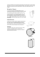
There are transmitters on the microphones that transmit an infrared signal. To ensure optimal performance, don’t cover or block the infrared transmitters. There must be a clear line of sight between the microphones and the infrared sensor in order for the audio system to work properly. Microphone Chargers If you use the included rechargeable batteries, you can recharge the microphones by connecting a microphone charger when the battery indicator light changes from green to red.
Installing Your SMART Audio 240 System This chapter helps you plan your installation and describes the installation process for your SMART Audio 240 system.
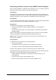
Determining the Best Location for Your SMART Audio 240 System Before you begin installation, consider the size and shape of your room, and then choose the best location for the receiver, speakers and ceiling infrared sensor. The Receiver The receiver is the central control unit of your audio system. Install it into a media rack (not included) with other electronics or in a location that’s accessible to the presenter and safe from tampering.
The Infrared Sensors You must choose to use either the receiver’s infrared sensor or the ceiling infrared sensor. Install one sensor and ensure the following: • There is a clear line of sight between the infrared sensor and the infrared transmitter on the microphones. • There are no wall or ceiling features, vents, projectors or other obstacles that block the sensor. NOTES – Direct sunlight can interfere with infrared signals. Position the sensors in areas that are shaded from direct sunlight.
Installing the Receiver Refer to the following diagram as you connect the cables to the receiver. PRE OUT Jack PRE OUT Volume Dial External Infrared Sensor Jacks Speaker Terminals Line 1 and 2 Jacks DC 15V 2.7A Jack To connect the power and speaker cables to the receiver 1. Connect the power supply to a power outlet, and then connect it to the DC 15V 2.7A jack on the back of the receiver. 2. Using a wire cutter, cut the plenum rated speaker cable to the length required to reach one of the speakers. 3.
To select the ceiling or the receiver infrared sensor 1. If you’ve connected an external sensor to EXT SENSOR INPUT 1, set the SENSOR SELECT switch on the side of the receiver to EXT. This disables the infrared sensor on the front of the receiver. OR Sensor Select Switch If you haven’t connected an external sensor to EXT SENSOR INPUT 1, set the SENSOR SELECT switch on the side of the receiver to INT. This disables the EXT SENSOR INPUT 1 connection on the back of the receiver.
3. Connect the RG-59 cable to the F-type jack on the ceiling sensor. F-Type Jack Screw Hole 4. Tighten two screws through the mounting bracket screw holes and into the ceiling using the appropriate screws for your ceiling. Installing the Ceiling Speakers Complete the following procedures for each ceiling speaker. To prepare a drop-ceiling tile for installation 1. Remove the ceiling tile that you want to install the ceiling speaker into. 2. Mark the center of the ceiling tile with a pencil. 3.
To attach the speaker cables to the ceiling speaker 1. Run the speaker wires from the receiver into the ceiling and to the ceiling speaker. WARNING Ensure that you bundle and mark cables extending across the floor to your SMART Audio 240 system to avoid a trip hazard. 2. Connect the positive cable to the speaker’s positive (red) terminal. 3. Connect the negative cable to the speaker’s negative (black) terminal.
Installing the Wall Speakers Complete the following procedures for each wall speaker. To attach a wall speaker to the wall 1. Place the wall speaker’s mounting bracket on the wall where you want to install the speaker. 2. If you’re attaching the speaker to a stud wall, use a carpenter’s level to straighten the bracket on the wall, and then tighten two screws appropriate for the stud through the bracket’s screw holes and into the stud.
Using Your SMART Audio 240 System This chapter describes how to use your audio system. Using the Receiver The following diagram shows you the different controls on the front of the receiver. Tone Dial Power Switch Infrared Sensor Microphone Channel A and B Volume Dials External Audio Line 1and 2 Volume Dials • Turn the power on or off with the POWER switch. • Use the CHANNEL A and B dials to adjust the microphones’ volume.
To use the handheld student microphone 1. Remove the battery cover by twisting the lower section of the microphone counter-clockwise, and then install the included AA batteries. NOTE: Ensure that the polarity of the batteries matches the polarity marked in the battery compartment. 2. Turn on the receiver’s power switch. 3. Set the channel switch on the handheld student microphone to Channel B. Channel A/B Switch High/Low Switch 4. Set the High/Low switch on the handheld student microphone to Low.
Using External Audio Devices You can use your audio system with a CD player, an MP3 player and a DVD player. To use a CD, MP3 or DVD player, or other audio device, with your audio system 1. Set up the external audio device. Refer to the device’s documentation for more information. 2. Connect an RCA cable to the left and right audio output jacks on the audio device. NOTE: If your audio device only has a 3.5 mm stereo mini jack, use a dual (left and right) RCA to 3.5 mm stereo adapter. 3.
5. Draw a small rectangle on the screen. 6. When you finish your recording, click Stop . The Save As dialog box appears. 7. Browse to the location where you want to save your recording. 8. Type a name for the file in the File name box. 9. Click Save. The Recording Complete dialog box appears. 10. Click OK.
Troubleshooting Your SMART Audio System Issue Solution The microphones do not work • Set the power switch on the receiver to ON. and the green power light is • Connect the receiver to a power outlet. not lit. • Rechargeable batteries eventually stop recharging. Replace the rechargeable batteries with a new set of rechargeable batteries. • Replace used alkaline batteries with a new set of alkaline batteries. The microphones do not work. • Turn up the volume dial on the receiver for the correct channel.
16 Troubleshooting Your SMART Audio System 99-00855-20 C0
99-00855-20 C0 Troubleshooting Your SMART Audio System 17
18 Troubleshooting Your SMART Audio System 99-00855-20 C0
Regulatory Compliance Waste Electrical and Electronic Equipment Regulations Waste Electrical and Electronic Equipment regulations apply to all electrical and electronic equipment sold within the European Union. When you dispose of any electrical or electronic equipment, including SMART products, we strongly encourage you to contact your local WEEE recycling agency for recycling and disposal advice. Your SMART product required the extraction and use of natural resources for its production.
20 Regulatory Compliance 99-00855-20 C0
Customer Support Online Support Visit www.smarttech.com/support to view and download user’s guides, “how-to” and troubleshooting articles, software and more. Training Visit www.smarttech.com/trainingcenter for training materials and information about our training services. Contacting SMART Technical Support SMART Technical Support welcomes your call. However, if you experience difficulty with your SMART product, you may want to contact your local reseller first.
Warranty Product warranty is governed by the terms and conditions of SMART’s “Limited Equipment Warranty” that shipped with the SMART product at the time of purchase. Registration To help us serve you, register online at www.smarttech.com/registration.
SMART Technologies 3636 Research Road N.W. Calgary, AB T2L 1Y1 CANADA www.smarttech.com/support www.smarttech.com/contactsupport Support +1.403.228.5940 or Toll Free 1.866.518.6791 (U.S.