SMART Room System™ for Microsoft® Lync® Setup and maintenance guide For models SRS-LYNC-S, SRS-LYNC-M and SRS-LYNC-L
Product registration If you register your SMART product, we’ll notify you of new features and software upgrades. Register online at smarttech.com/registration. Keep the following information available in case you need to contact SMART Support. Serial numbers: Interactive flat panel(s)* Lync® appliance Console Camera Table microphones Audio processor Speakers Date of purchase: * When requesting technical support, provide SMART Support with the left interactive flat panel’s serial number.
Important information IMPOR TA N T If you were directed to this guide from your room system’s quick start guide, proceed to Configuring your room system’s software on page 11. WARNING l Failure to follow the installation instructions sent with your SMART product could result in personal injury and product damage which may not be covered by your warranty. l Ensure that your installation complies with local building and electrical regulations. l Do not open or disassemble the SMART product.
IMPORT ANT INF ORMAT ION l Do not move or mount the interactive flat panel by connecting rope or wire to its handles. Because the interactive flat panel is heavy, rope, wire or handle failure could lead to personal injury. l Use SMART supplied mounting hardware or hardware that is designed to properly support the weight of your product.
Contents Important information i Chapter 1: Welcome 1 About your room system About this guide Other documentation and resources Chapter 2: Installing your room system’s hardware Chapter 3: Configuring your room system’s software Before configuring your room system’s software Turning on your room system for the first time Logging on and configuring the displays Configuring Lync Room System software Checking the status of the Lync Room System software product key Configuring SMART Settings Making a test c
CONT ENT S Appendix A: Using the interactive flat panel on-screen display menu Accessing the on-screen display menu Changing settings in the on-screen display menu Small and large room on-screen display menu Medium room on-screen display menu 51 51 52 52 57 Appendix B: Resetting the room system to factory defaults 65 Appendix C: Hardware environmental compliance 67 Waste Electrical and Electronic Equipment and Battery regulations (WEEE and Battery Directives) Batteries More information Index iv 67
Chapter 1 Welcome About your room system Features Integration with Lync Simple startup Automatic sharing of video and audio Collaboration Presence detection Components SMART Board interactive flat panels Lync appliance Console Camera Microphones Speakers Video connection harness for guest laptops Table microphone upgrade kit Accessories Wall stand kit Table microphones Comparing small, medium and large rooms About this guide Other documentation and resources Specifications Installation instructions Deploym
CHAPTER 1 Welcome Using the installed Lync Room System software, you can start a meeting and connect with other individuals or meeting rooms with a single tap on the console or the interactive flat panels. You can write or draw on the interactive flat panels using the whiteboard feature, connect an optional guest laptop to share its screen and share files with connected individuals and meeting rooms in real time. Features Your room system includes the following features.
CHAPTER 1 Welcome Components Your room system consists of the following major components: Part no.
CHAPTER 1 Welcome Lync appliance The Lync appliance includesLync Room System software as well asSMART Product Drivers . Lync Room System software enables users to start, join and facilitate meetings and connect with others through your organisation’sLync infrastructure. SMART Product Drivers enables the touch features of the interactive flat panels and the operation of all the components in the room system. The Lync appliance is installed in a slot on the bottom of the interactive flat panel.
CHAPTER 1 Welcome Speakers The speakers transmit audio from remote participants during a meeting. The room system’s audio-processing features eliminate echos and in-room audio feedback. The speakers are installed on either side of the interactive flat panels. Video connection harness for guest laptops The video connection harness enables users to connect their laptops to the room system using either VGA or HDMI connectors.
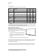
CHAPTER 1 Welcome Comparing small, medium and large rooms The SMART Room System comes in three sizes: Small (SRS-LYNC-S) Medium (SRS-LYNC-M) Large (SRS-LYNC-L) The following table presents the key differences between the small, medium and large room sizes: Small room Medium room Large room Small meeting rooms (approximately six people) Medium meeting rooms (approximately 12 people) Large meeting rooms (approximately 16 people) 10 m² (100 sq ft ) 20 m² (180 sq ft ) 30 m² (300 sq ft ) Display ty
CHAPTER 1 Welcome This guide is intended for individuals who are responsible for installing and maintaining room systems in their organisations. Other documentation and resources are available for individuals who use room systems. Other documentation and resources In addition to this guide, there are resources for individuals who install, maintain and use room systems.
CHAPTER 1 Welcome Deployment and remote management instructions Microsoft provides documentation on how to deployLync software and remotely manageLync Room System software usingLync Infrastructure Environment Administrator tools such as theLync control console and SCOM. l microsoft.com/en-us/download/details.aspx?id=39274 l microsoft.com/en-us/download/details.aspx?id=29256 User documentation and training Lync Meeting Room software includes a tutorial that explains how to use the software.
Chapter 2 Installing your room system’s hardware This chapter is intended for installers. Before they install the room system’s hardware, installers should read this chapter along with the hardware installation instructions (see Installation instructions on page 7) included with the room system. WARNING Improper installation of your room system’s hardware can result in personal injury and product damage.
CHAPTER 2 Installing your room system’s hardware l Choose an appropriate location for the room system: o Do not install the room system in a location where a door or gate could hit it. o Do not install the room system in an area where it will be subjected to strong vibrations or dust. o Do not install the room system where the main power supply enters the building.
Chapter 3 Configuring your room system’s software Before configuring your room system’s software Turning on your room system for the first time Logging on and configuring the displays Configuring Lync Room System software Checking the status of the Lync Room System software product key Configuring SMART Settings Making a test call 11 12 15 17 18 18 20 After completing the hardware installation, you must turn on the room system for the first time and then configure its software.
CHAPTER 3 Configuring your room system’s software l You have the necessary information to connect the room system to the Lync Server, including the following: o IP addresses for DNS servers (if not configured automatically from the network via DHCP) l o Administrator user name and password to be applied to the room system o Lync appliance computer name for network presence o Lync account name and password for the room system o SIP URI address A USB mouse and keyboard are connected to the Lync a
CHAPTER 3 Configuring your room system’s software 2. Press the Input Select button input source isHDMI 3/PC. on the interactive flat panel’s front control panel until the N OTE In large room installations, set the input source to HDMI3/PC for both interactive flat panels. The Lync appliance starts and completes the first-run installation process. During this process, the Lync appliance restarts several times. N OTE This process takes time to complete.
CHAPTER 3 Configuring your room system’s software 3. Configure the interactive flat panels’ on-screen display menus: Room Small (without the table microphone upgrade kit) Procedure a. Press MENU on the interactive flat panel’s remote control. b. Press the down arrow until you select the SETUP menu and then press SET. c. Press the down arrow until you select Lync® ROOM RESETand then press SET. d. Press MENU, press the up arrow until you select the AUDIO menu and then press SET. e.
CHAPTER 3 Configuring your room system’s software To configure Lync Room System software first-run installation settings 1. Select your language and then click Next. 2. Select your country or region, time and currency preference, and keyboard layout, and then click Next. 3. Type a user name for the administrator account and a computer name for the Lync appliance and then click Next. N OTES o Follow your organisation’s standard for assigning user names and computer names.
CHAPTER 3 Configuring your room system’s software 3. If you’re configuring the software for a small room without the table microphone upgrade kit, select Use the camera microphone and then click OK. OR If you’re configuring the software for a small room with the table microphone upgrade kit, a medium room or a large room, select Use the table microphone and then click OK. IMPOR TA N T o You are unable to change this setting later, so ensure that you select the correct option.
CHAPTER 3 Configuring your room system’s software 6. Click OK in Control Panel and then click OK in second dialogue box. The Lync appliance checks the display configuration: o If there are major errors, a dialogue box appears. Repeat this procedure to correct the errors. o If there are no major errors, Lync Room System software starts. Continue to the next procedure.
CHAPTER 3 Configuring your room system’s software 6. Select Obtain DNS server address automatically. OR Select Use the following DNS server addresses and then type your domain’s DNS server addresses in thePreferred DNS server and Alternate DNS server boxes. 7. Select Validate settings upon exit and then click OK. 8. Click Password Renewal and then disable Auto-Renew Password. 9. Continue to the next procedure.
CHAPTER 3 Configuring your room system’s software 3. For each interactive flat panel, do the following: a. Select the interactive flat panel from the list and then click Next. b. Select Product is being set up for the first time and then click Next. The calibration screen appears on the selected interactive flat panel.
CHAPTER 3 Configuring your room system’s software 6. Click OK. SMART Settings closes. 7. Continue to the next procedure. Making a test call To make a test call 1. Click Lync Settings and then click Make a Test Call. Lync Room System software makes a test call. 2. If the audio is too loud or too quiet, adjust the audio settings in the Lync Settings tab. 3. If adjusting the audio settings in the previous step didn’t resolve your audio issues, do the following: a.
Chapter 4 Using your room system Scheduling meetings Turning on your room system Starting meetings and whiteboard sessions Managing meetings using the console Presenting content during meetings Presenting computer screens Presenting files Using the whiteboard feature Ending meetings 21 22 22 24 26 26 26 27 28 This chapter provides an overview of how users can schedule and conduct a meeting using your SMART Room System and Lync Room System software.
CHAPTER 4 Using your room system 4. If appropriate, make the meeting private so that participants must enter a password to join: a. Click Meeting Options. The Lync Meeting Options dialogue box appears. b. Click Permissionsand then select A new meeting space (I control permissions). c. Select who to permit as participants, who to permit as presenters, and any limitations on presenters. d. Click OK. 5. Send the meeting invitation to the participants and resources.
CHAPTER 4 Using your room system N OTE If the room system’s schedule doesn’t appear or update correctly, there might be an issue with the connection between the Lync Room System software and Microsoft Exchange server (see Resolving software issues on page 49). Users can join a scheduled meeting when the room system is booked, or they can create an ad hoc meeting or an ad hoc whiteboard session when the room system is available. To join a scheduled meeting 1.
CHAPTER 4 Using your room system 3. Press Email Whiteboard when done to email the whiteboard file. Managing meetings using the console The console enables users to manage the meeting and the room system features. The user who organised the meeting typically sits in front of and operates the console during the meeting.
CHAPTER 4 Using your room system Tab Contents Display Display options for the room system’s interactive flat panels Actions l l l IM Instant messages (IMs) shared during the meeting In small and medium rooms, select from one of the following options: o Gallery & Content to show the gallery and shared content o Gallery to show only the gallery o Presentation to show only shared content o Speaker to show only the presenting participant’s video o Speaker & Content to show the presenting part
CHAPTER 4 Using your room system Button Procedure Email Whiteboard Email the whiteboard file. Leave Meeting Disconnect the room system from the Lync meeting (see Ending meetings on page 28).
CHAPTER 4 Using your room system To share a PowerPoint file, the user clicks Presentation in Lync software and then selects PowerPoint. By default, other users can write or draw over the PowerPoint file but must click Content and then select Take Over as Presenter (on the console) or press the arrow buttons and then press Yes when prompted to take over as the presenter (on interactive flat panels) before doing so.
CHAPTER 4 Using your room system Ending meetings At the end of the meeting, users can press Leave Meeting on the console to disconnect the room system from the Lync meeting. The Lync meeting ends when all participants have left.
Chapter 5 Maintaining your room system Recommended tools Turning off your room system Updating software and firmware Maintaining the interactive flat panels Calibrating the interactive flat panels Orientating the interactive flat panels Cleaning the screens Cleaning the presence detection sensors Cleaning the camera windows and reflective tape Maintaining ventilation Preventing condensation Replacing a pen nib Using the kickstands to access connectors Maintaining the console Maintaining the camera Maintain
CHAPTER 5 Maintaining your room system Recommended tools The following are recommended tools that professional, trained installers and IT specialists should have available for maintenance and troubleshooting purposes: Activity Hardware service Recommended tools l Paper and pencil l Ladder l Tape measure l Hardware isolation testing l Flashlight l Nylon cable ties l Cable tie cutter l 5m (16' 5") USB cable l 5m (16' 5") USB cable with mini-B connector l 5m (16' 5") active USB extension c
CHAPTER 5 Maintaining your room system Turning off your room system For some maintenance procedures, you need to turn off your room system. To turn off your room system 1. On the console, press Options and then press Restart. 2. When the screens are blank or when the SMART logo appears, use the power switches on the bottoms of the interactive flat panels to turn off the room system.
CHAPTER 5 Maintaining your room system Maintaining the interactive flat panels Complete the following tasks on a regular basis to maintain your room system’s interactive flat panels: l Calibrate and orientate the interactive flat panels as necessary l Clean the screen l Clean the presence detection sensors l Clean the camera windows and reflective tape l Maintain ventilation l Prevent condensation l Replace pen nibs as necessary Calibrating the interactive flat panels Digital cameras in the c
CHAPTER 5 Maintaining your room system 3. Type the room system administrator account’s user name and password and then press ENTER. The Settings screen appears. 4. Press OEM Settings and then press SMART Board Settings. SMART Settings appears. 5. Press SMART Hardware Settings. 6. Select the interactive flat panel you want to calibrate. 7. Select Advanced Settings from the drop-down list. 8. Press Calibrate. The calibration screen appears. This can take a few moments.
CHAPTER 5 Maintaining your room system Orientating the interactive flat panels Typically, you need to orientate the interactive flat panels during initial configuration only (see Configuring SMART Settings on page 18). However, you might need to orientate the interactive flat panels again if the location of users’ touch is misinterpreted (a pointer appears a distance from the actual contact or on a different display than the one being touched).
CHAPTER 5 Maintaining your room system Cleaning the screens Follow these instructions to clean the interactive flat panels’ screens without damaging their anti-glare coating or other product components. C A U TION l Do not use permanent or dry-wipe markers on the screens. If dry-wipe markers are used on the screens, remove the ink as soon as possible with a lint-free, non-abrasive cloth. l Do not rub the screens with a dense or rough material. l Do not apply pressure to the screens.
CHAPTER 5 Maintaining your room system C A U TION l Do not use compressed air to clean the camera windows or borders. l Do not use water, chemicals or cleaning agents. l Applying too much pressure when cleaning the tape or cameras can damage the tape and cameras and cause performance issues or errors. To clean the camera windows and reflective tape 1.
CHAPTER 5 Maintaining your room system 4. If the screen condensation doesn’t evaporate, contact SMART Support (smarttech.com/contactsupport). Replacing a pen nib To prevent damage to your interactive flat panels’ anti-glare coating, replace a pen nib if it becomes worn. Replacement pen nibs are included with your room system, and you can purchase additional replacements from your authorised SMART reseller (smarttech.com/where) or the SMART Parts Store (parts.smarttech.com). To replace a pen nib 1.
CHAPTER 5 Maintaining your room system 3. Deploy the kickstands by pushing them up and towards the wall. N OTE When you’ve completed your maintenance or troubleshooting and no longer need access to the connectors, push the kickstands down, push the locks up and then place the interactive flat panel back in its original position. Maintaining the console Follow these instructions to clean the console’s screen without damaging its anti-glare coating or other product components.
CHAPTER 5 Maintaining your room system You need to clean the camera lens only if there is visible accumulation of dust. Use a canister of inert gas or a blower bulb to blow the dust off of the lens. Don’t blow off dust with your mouth because this can deposit droplets of saliva on the camera lens. Maintaining the microphones Follow these instructions to clean the microphones. To clean the microphones 1. Turn off your room system (see Turning off your room system on page 31). 2.
CHAPTER 5 Maintaining your room system Removing and transporting your room system WARNING Only professional, trained installers should remove your room system. C A U TION l Save your original packaging so that you can repack your room system with as much of the original packaging as possible. This packaging was designed with optimal shock and vibration protection. If your original packaging isn’t available, you can purchase the same packaging directly from your authorised SMART reseller (smarttech.
Chapter 6 Troubleshooting your room system Resolving hardware issues Locating serial numbers Locating power and status lights Resolving issues with the interactive flat panels Resolving issues with the console Resolving issues with the camera Resolving issues with the microphones Resolving issues with the speakers Resolving issues with connected laptops Resolving software issues Testing your room system Accessing SMART Settings 41 42 42 43 46 46 47 47 48 49 49 50 This chapter provides you with the inform
CHAPTER 6 Troubleshooting your room system Locating serial numbers Each of the major components of your room system has a serial number. Component Serial number location Interactive flat panel Back of the interactive flat panel in the top right-hand corner N OTES l l When requesting technical support, provide SMART Support with the left interactive flat panel’s serial number.
CHAPTER 6 Troubleshooting your room system No. Component Light 1 Interactive flat panel Power 2 Interactive flat panel Touch system status 3 Console Power and status 4 Camera Video capture 5 Camera Service 6 Camera Microphone (if camera-integrated microphones used) 7 Microphones Microphone (if table microphones used) 8 Speakers Power N OTE The Lync appliance includes power and hard drive activity lights (not shown).
CHAPTER 6 Troubleshooting your room system Power light Touch system status light Interactive flat panel status Issues Solid amber Off Standby mode The interactive flat panel doesn’t turn on when you enter the room. Solutions l l l l The interactive flat panels are turning on after they’ve been turned off. l l The interactive flat panels are turning on when people aren’t present. l l Enable presence detection (see page 56 for small and large rooms orpage 62 for medium rooms).
CHAPTER 6 Troubleshooting your room system Power light Touch system status light Interactive flat panel status Issues Solutions The image is unstable or unfocused. Secure the HDMI cable at both connection points. The image is too light, too dark or has poor quality issues. Press AUTO SETUP (small and large rooms) or AUTO (medium rooms) on the interactive flat panel’s remote control to automatically configure the video settings. There is a persistent image on the screen.
CHAPTER 6 Troubleshooting your room system Resolving issues with the console Use the following table to resolve issues with your room system’s console. Power light Console status Issues Solutions Off Not receiving power The console should be receiving power but isn’t. Ensure that the console is connected to the power supply as shown in the installation instructions (see page 7).
CHAPTER 6 Troubleshooting your room system Video capture light Service light Camera status Issues Solutions Red Green On but not capturing video The camera’s video output doesn’t appear even though it should. Perform a room system test (see page 49). Green Green On and capturing video The camera’s video output doesn’t appear. Open the privacy shutter. (The privacy shutter is marked with a red spot to indicate when it’s closed.) The video quality is poor.
CHAPTER 6 Troubleshooting your room system Power light Speaker status Issues On On You’re unable to hear sound. Solutions l l l Unmute the audio in Lync Room System software. Turn up the volume in Lync Room System software. For small rooms without the table microphone upgrade kit, ensure the audio input is set to HDMI3/PC ANALOGUE (seepage 54). For small rooms with the table microphone upgrade kit, ensure that the audio input is set to IN2 (see page 54).
CHAPTER 6 Troubleshooting your room system Resolving software issues If the Lync Room System software calendar doesn’t appear on the console and interactive flat panels, or if it indicates that the room is free for 24 hours when you know that is has been booked for meetings, there is an issue with the connection between the room system and your organisation’s Microsoft Exchange server. For assistance with these and other network issues, contact your organisation’s network administrator.
CHAPTER 6 Troubleshooting your room system 5. Press Make a Test Call and then follow the on-screen instructions to test call functions. OR Press Test Meet Now and then follow the on-screen instructions to test server connections and video functions. Accessing SMART Settings You might need to access SMART Settings for some troubleshooting procedures. N OTE To access SMART Settings, you need the room system administrator account’s user name and password. To access SMART Settings 1.
Appendix A Using the interactive flat panel on-screen display menu Accessing the on-screen display menu Changing settings in the on-screen display menu Small and large room on-screen display menu Medium room on-screen display menu 51 52 52 57 You can access the on-screen display menu using either the remote control or the menu control panel.
APPENDIX A Using the interactive flat panel on-screen display menu To replace batteries in the remote control 1. Press the tab on the underside of the remote control and then open the cover. 2. Remove the existing batteries. 3. Insert two new 1.5V AAA batteries in the remote control. 4. Replace the cover. Changing settings in the on-screen display menu To change settings in the on-screen display menu 1. Press the MENU button on the remote control or the menu control panel.
APPENDIX A Using the interactive flat panel on-screen display menu Option Values Function Notes (if any) BRIGHTNESS 0–100 Sets the overall brightness of the image and background You can modify this option only if you select USER in PICTURE MODE. CONTRAST 0–100 Sets the brightness of the image in relation to the background You can modify this option only if you select USER or AMBIENT in PICTURE MODE.
APPENDIX A Using the interactive flat panel on-screen display menu Option IN BRIGHT LUX Values Function Notes (if any) 100–1000 Sets the illuminance level for brightly lit rooms (in lux) You can modify this option only if you select AMBIENT in PICTURE MODE. The value of this menu option can’t be less than the value of IN DARK LUX. IN DARK LUX 50–950 Shows the illuminance level for dimly lit rooms (in lux) You can modify this option only if you select AMBIENT in PICTURE MODE.
APPENDIX A Using the interactive flat panel on-screen display menu Option Values Function Notes (if any) ON Enables or disables the right speaker Don’t change this option from its default value. [N/A] Resets all options in the AUDIO menu to their default values This option isn’t applicable to the SMART Room System. Don’t change it from its default value.
APPENDIX A Using the interactive flat panel on-screen display menu Option MONITOR ID Values Function Notes (if any) 1–100 Sets the interactive flat panel’s ID This option isn’t applicable to the SMART Room System. Don’t change it from its default value. ENABLE Enables or disables presence detection You can modify this option only if you select STANDBY in STANDBY MODE.
APPENDIX A Using the interactive flat panel on-screen display menu Option Values Function Notes (if any) VGA1 Sets the video input for the USB1 port, or disables the port This option isn’t applicable to the SMART Room System. Don’t change it from its default value. Sets the video input for the USB2 port, or disables the port This option isn’t applicable to the SMART Room System. Don’t change it from its default value.
APPENDIX A Using the interactive flat panel on-screen display menu Option In Bright Values Function Notes (if any) 1–100 Sets the image brightness for brightly lit rooms You can modify this option only if you select Ambient in Picture Mode. The value of this menu option can’t be less than the value of In Dark. In Dark 0–99 Sets the image brightness for dimly lit rooms You can modify this option only if you select Ambient in Picture Mode.
APPENDIX A Using the interactive flat panel on-screen display menu Option Sky Colour Super Resolution Gamma Values Function -5–5 Sets the preferred colour value for sky in the image On Off Enables or disables super resolution Low Sets the gamma Notes (if any) Medium Hight Picture Option Noise Reduction Low Sets image noise reduction This option isn’t applicable to the SMART Room System. Don’t change it from its default value.
APPENDIX A Using the interactive flat panel on-screen display menu Option Screen Values Function Notes (if any) [N/A] Shows the current input type This option only provides information. You’re unable to modify it. Standard Sets the sound mode This option isn’t applicable to the SMART Room System. Don’t change it from its default value. Enables or disables virtual surround sound This option isn’t applicable to the SMART Room System. Don’t change it from its default value.
APPENDIX A Using the interactive flat panel on-screen display menu Option Values Function Notes (if any) HDMI3/PC Specifies a video input to map to AUDIO2 or disables AUDIO2 This option should be set to HDMI3/PC for the SMART Room System. Specifies a video input to map to AUDIO3 or disables AUDIO3 This option isn’t applicable to the SMART Room System. Don’t change it from its default value.
APPENDIX A Using the interactive flat panel on-screen display menu Option Sleep Timer Values Function Notes (if any) 10–240 Specifies the amount of inactivity (in minutes) before the interactive flat panel turns off, or disables the sleep timer feature This option isn’t applicable to the SMART Room System. Don’t change it from its default value.
APPENDIX A Using the interactive flat panel on-screen display menu Option Ready State Brightness Values Function Notes (if any) 0–100 Sets the brightness of the welcome screen This option isn’t applicable to the SMART Room System. Don’t change it from its default value. HDMI1 Sets the video input for the USB1 port, or disables the port Don’t change this option from its default value.
Appendix B Resetting the room system to factory defaults This appendix explains how to reset the room system to factory defaults. In most situations, you should reset the room system from the Settings screen. However, if the room system is in an unrecoverable state or the Settings screen is otherwise not accessible, you can reset the room system from the BIOS. To reset the room system from the Settings screen 1. On the console, press Options and then press Settings.
APPENDIX B Resetting the room system to factory defaults To reset the room system from the BIOS 1. Connect a USB keyboard to the Lync appliance. 2. Turn on the room system using the power switch located on the bottom of the interactive flat panel. Small room Medium room Large room (×2) N OTE In large room installations, turn on both interactive flat panels. 3. Press the DELETE key. The Lync appliance enters BIOS mode. 4. Browse to the Advanced tab 5. Select Recovery Functionand then press ENTER. 6.
Appendix C Hardware environmental compliance SMART Technologies supports global efforts to ensure that electronic equipment is manufactured, sold and disposed of in a safe and environmentally friendly manner. Waste Electrical and Electronic Equipment and Battery regulations (WEEE and Battery Directives) Electrical and electronic equipment and batteries contain substances that can be harmful to the environment and to human health.
Index A accessories 5 ad hoc meetings 23 administrator accounts 15 air conditioning 10, 36 ambient lighting 53 annotations 26 audio configuring 54, 60 maintaining 39 sharing 2 troubleshooting 20, 47 B backlight 58 batteries 51, 67 black level 53, 59 brightness 53, 58 C cable ties 30 cable tracking 5 cables for hardware isolation testing 30 calibration 18, 32, 34, See also orientation calls converting to meetings 23 making test 20, 49 cameras about 4 cleaning 38 optimizing 19 troubleshooting 46 chemicals 3
INDEX F L factory defaults 65 field of view 4 firmware updates 31 flashlights 30 ladders 30 languages 55 laptops 5, 26, 48 large rooms 6 licenses See product keys lights 42 local building regulations 9 location for installing your room system 10 Lync appliances 4, 11 Lync infrastructure 2, 11 Lync Room System software about 2 configuring 17 product key for 18 troubleshooting 49 using 21 G gallery of participants 25 gates 10 glass cleaner 35, 38 guest laptops See laptops H hardware installation 9, 39 h
INDEX Microsoft Lync Room System software See Lync Room System software Microsoft Outlook 21 Microsoft PowerPoint 2, 26 mouse 11 mute 25 N network requirements 11 nylon cable ties 30 O on-screen display menu 51 on-screen keyboard 25 orientation 18, 32, 34, See also calibration Outlook See Microsoft Outlook P packaging 40 participants, meeting 24 passwords 15 pens, replacing nibs for 37 permanent markers 35 phone features 23, 25 power 10 power lights 42 prerequisites 11 presence detection sensors about 2
INDEX T table microphone upgrade kit 5 tape measures 30 test calls 20, 49 tint 53, 58 tools, recommended 30 touch panels See interactive flat panels training 8 transportation 40 troubleshooting 41 U user names 15 V vacuum cleaners 36 ventilation 10, 36 VGA 5, 48 vibration 10, 40 video connection harness 5 videos 2, 4, 25, See also cameras volume 20, 25, 47 W wall stand kits 5 water 36 WEEE and Battery Directives 67 whiteboard feature 2, 27 writing 26 72
SMART Technologies smarttech.com/support smarttech.