
User's Manual
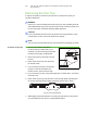

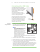
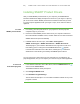
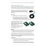
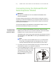
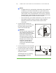
Table Of Contents
- Product Registration
- Important Information
- Contents
- About Your SMART Board 600 or SBD600 Series Interactive Whiteboard
- In This Chapter
- Features
- How Does Your SMART Board Interactive Whiteboard Work?
- Included Accessories
- Optional Accessories
- Serial RS-232 Expansion Module
- The serial expansion module connects to the controller module on the back of your interactive whiteboard.
- Wireless Bluetooth Connection
- SystemOn Expansion Module
- USB Audio System
- Active USB Extension Cables
- Projector Wall-Mount (Models 680 and SBD680 only)
- SMART Board Interactive Whiteboard Floor Stand (Models 640, 660, 680 and SBD680 only)
- SMART Board Interactive Whiteboard Table Stand
- Installing and Securing Your SMART Board Interactive Whiteboard
- In This Chapter
- Environmental Requirements
- Mounting Your SMART Board 660, 680 or SBD680 Interactive Whiteboard on a Floor Stand
- Wall-Mounting Your SMART Board Interactive Whiteboard
- Securing the Pen Tray and Interactive Whiteboard
- Removing the Pen Tray
- Connecting Your Interactive Whiteboard to Your Computer
- In This Chapter
- Overview
- System Power Safety and Precautions
- Connecting with a USB Cable
- Installing SMART Product Drivers
- Connecting Using the Optional RS-232 Serial Expansion Module
- Connecting with the Wireless Bluetooth Connection Option
- Configuring Your Computer Settings
- Orienting Your Interactive Whiteboard
- Connecting a Guest Laptop
- Connecting Multiple Interactive Products
- Using and Maintaining Your SMART Board Interactive Whiteboard
- Troubleshooting Your SMART Board Interactive Whiteboard
- In This Chapter
- Adjusting the Projected Image
- Resetting Your Interactive Whiteboard
- Troubleshooting Using the Ready Light
- Flowchart 1: Getting Started
- Flowchart 2: Ready Light Off
- Flowchart 3: Ready Light Red
- Things to try first:
- • Disconnect and then reconnect the USB cable at both ends to reset your interactive whiteboard and reestablish the link.
- • If the Ready light changes from green to red while your computer is running, the computer might become unresponsive. Restart your computer.
- • An alternating red/green light might indicate that your computer is running too many other applications or doesn’t meet minimum specifications. Reduce the load on your computer by closing unnecessary applications, or replace it with a more powe...
- Things to try first:
- Flowchart 4: Ready Light Flashing Green
- Flowchart 5: Ready Light Steady Green
- A steady green Ready light indicates that the controller is operating normally. If the pen tray failed or isn’t communicating with the controller, your interactive whiteboard will still operate in mouse mode. When you reset your interactive whitebo...
- Troubleshooting Tips
- Where to Find More Information
- Contacting SMART Technical Support
- Hardware Environmental Compliance
- Customer Support
- Index

23 | INSTALLING AND SECURING YOUR SMART BOARD INTERACTIVE
WHITEBOARD
IMPORTANT
Be aware that security cable locks are not designed to be a solid protection
measure because the lock can be torn out. However, potential thieves might be
reluctant to try to sell a product with a broken security cable lock hole, which
would readily identify it as a stolen item.
To lock the pen tray
to your interactive
whiteboard
1. Loop your security cable behind the pen tray brackets before you secure them
to the wall, as shown in step 3 on page 21.
2. Thread the lock end of the cable through the loop end of the cable.
3. Verify that the cable is tight enough that you can’t remove the pen tray while the
lock is in place, and then install the pen tray.
4. Insert the prong end of the security cable into the lock slot, and then complete
the pen tray installation by securing it to the wall.
Securing the Pen Tray to the Pen Tray Brackets
Since you can remove the pen tray without tools, you might want to securely attach it
to its brackets. To do this, insert two No. 8/M4 screws (not included) into the holes
indicated in the following illustration.
NOTE
Older units don’t include this feature.
Screw Location