SMART Board® 800i6 Interactive whiteboard systems Configuration and user’s guide
FCC warning This equipment has been tested and found to comply with the limits for a Class A digital device, pursuant to Part 15 of the FCC Rules. These limits are designed to provide reasonable protection against harmful interference when the equipment is operated in a commercial environment. This equipment generates, uses and can radiate radio frequency energy and, if not installed and used in accordance with the manufacturer’s instructions, may cause harmful interference to radio communications.
Important information Before you install and use your SMART Board® 800i6 interactive whiteboard system, read and understand the safety warnings and precautions in this user’s guide and the included warnings document. These safety warnings and precautions describe the safe and correct operation of your interactive whiteboard system and its accessories, helping you to prevent injuries and equipment damage. Ensure that your interactive whiteboard system is always being used correctly.
IMPORT ANT INF ORMAT ION l Two people are required to mount your SMART product because it may be too heavy for one person to safely maneuver. When you lift your interactive whiteboard, you and your assistant should stand on either side of the screen, supporting its weight at the bottom while balancing the top with your other hands. l When mounting the projector boom on a framed or hollow wall, attach the mounting bracket to a stud to safely support the projector’s weight.
IMPORT ANT INF ORMAT ION l You must connect the USB cable that came with your SMART Board interactive whiteboard to a computer that has a USB compliant interface and that bears the USB logo. In addition, the USB source computer must be compliant with CSA/UL/EN 60950 and bear the CE mark and CSA and/or UL Mark(s) for CSA/UL 60950. This is for operating safety and to avoid damage to the SMART Board interactive whiteboard.
IMPORT ANT INF ORMAT ION C A U TION l Do not block the projector’s ventilation slots and openings. l If dust or small items prevent pen tray buttons from being pressed or cause constant button contact, remove the obstructions carefully. IMPOR TA N T l Keep your remote control in a safe place because there is no other way to access menu options. l Do not disconnect cables from the ECP to connect peripheral devices because you could disconnect controls for your interactive whiteboard.
IMPORT ANT INF ORMAT ION Environmental requirement Dust Parameter l Electrostatic discharge (ESD) l l l Cables Conducted and radiated emissions v l l smarttech.com/kb/170401 Intended for use in office and classroom environments. Not for industrial use where heavy dust and pollutants can cause malfunctions or impaired operation. Periodic cleaning is required in areas with heavier dust. See Cleaning the projector on page 35 for information on cleaning the projector.
Contents Important information i Safety warnings, cautions and important information Environmental requirements i iv Chapter 1: About your interactive whiteboard system 1 SMART Board 800i6 interactive whiteboard system features Included accessories Chapter 2: Installing your interactive whiteboard system Choosing a location Choosing a height Securing your interactive whiteboard system Routing the cables Installing SMART software Chapter 3: Using your interactive whiteboard system Using your projector
CONT ENT S Appendix A: Remotely managing your system through a network interface Web page management Simple Network Management Protocol (SNMP) Appendix B: Remotely managing your system through an RS-232 serial interface Connecting your room control system to the ECP Projector programming commands 57 57 65 67 68 69 Appendix C: Remote control code definitions 97 Appendix D: Hardware environmental compliance 99 Waste Electrical and Electronic Equipment and Battery regulations (WEEE and Battery Directive
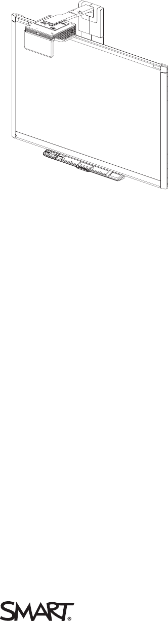
Chapter 1 About your interactive whiteboard system SMART Board 800i6 interactive whiteboard system features SMART Board 800 series interactive whiteboard SMART UF70 or SMART UF70w projector Extended Control Panel (ECP) Included accessories Remote control Pens Eraser VGA connection kit SMART Board 800i6 interactive whiteboard system accessories RCA connector pod Your SMART Board 800i6 interactive whiteboard system combines the following components: l SMART Board 800 series interactive whiteboard l Wall-
CHAPTER 1 About your interactive whiteboard system SMART Board 800i6 interactive whiteboard system features Your SMART Board 800i6 interactive whiteboard system uses the short-throw, high-offset SMART UF70 or SMART UF70w projector. The throw distance of the SMART UF70 or SMART UF70w projectors is half that of the SMART UF65 projector, resulting in a shorter boom and reduced shadows on the projected image.
CHAPTER 1 About your interactive whiteboard system Other features of your interactive whiteboard include: l A modular pen tray that automatically detects when you pick up a pen tray pen or the eraser l Pen tray buttons that activate the pens’ colors and the on-screen keyboard, right-click, Orientation and Help functions l A durable hard-coated surface that is optimized for projection and easily cleaned l A security cable lock feature that enables you to lock your interactive whiteboard to help safeg
CHAPTER 1 About your interactive whiteboard system l A secure mounting and installation system that includes the following: o An optional projector padlock ring to prevent removal of the projector from the boom o Accessory mounting hardware for solid masonry or framed wall installations kit part number 1007416 o Templates and instructions for positioning the system safely Projector information Extended Control Panel (ECP) Your projector system ECP attaches to the interactive whiteboard pen tray.
CHAPTER 1 About your interactive whiteboard system Eraser The eraser resembles a rectangular chalkboard eraser. You can use a substitute object, as long as it has a similar shape, reflects infrared light and doesn’t scratch or mark the interactive whiteboard surface. VGA connection kit The VGA connection kit allows you to connect a laptop to your interactive whiteboard system using a VGA cable.
Chapter 2 Installing your interactive whiteboard system Choosing a location Choosing a height Securing your interactive whiteboard system Locking the pen tray to your interactive whiteboard Securing the projector to the boom Routing the cables Installing SMART software 8 8 9 9 9 9 10 Consult the SMART Board 800i6 interactive whiteboard system installation document included with your product for instructions on how to install and secure your system.
CHAPTER 2 Installing your interactive whiteboard system Choosing a location Choose a location for your interactive whiteboard system that’s far from bright light sources, such as windows and strong overhead lighting. Bright light sources can cause distracting shadows on your interactive whiteboard and can reduce the contrast of the projected image. Select a wall with a flat, regular surface and sufficient clearance to accommodate your interactive whiteboard system.
CHAPTER 2 Installing your interactive whiteboard system l Position the projector at the correct height above your interactive whiteboard to align the projected image with the touch screen. Dimensions on the template recommend a distance from the floor suitable for adults of average height. You should consider the general height of your user community when you choose a location for your interactive whiteboard.
CHAPTER 2 Installing your interactive whiteboard system Cable routing for SMART Board 880 interactive whiteboards Cable routing for SMART Board 885 interactive whiteboards IMPOR TA N T Do not connect the power cable to a power outlet until you have connected all the cables to the projector and ECP.
Chapter 3 Using your interactive whiteboard system Using your projector Using your remote control Replacing the remote control battery Using the remote control buttons Adjusting projector settings Focusing the image Adjusting the image Projector connection diagram Using your interactive whiteboard Using the Extended Control Panel (ECP) Using the RCA connector pod 11 11 12 13 14 20 21 21 23 23 25 This chapter describes the basic operation of your interactive whiteboard system and explains how to set up yo
CHAPTER 3 Using your interactive whiteboard system Replacing the remote control battery Follow this procedure to replace the remote control battery. WARNING l Reduce the risk associated with a leaking battery in the projector’s remote control by following these practices: o Use only the specified CR2025 coin-cell battery. o Remove the battery when the remote control is unused for an extended period. o Do not heat, disassemble, short or recharge the battery, or expose it to fire or high temperatures.
CHAPTER 3 Using your interactive whiteboard system Using the remote control buttons The projector remote control enables you to access on-screen menus and change projector settings. Use the Power button on the remote control or ECP to put the projector into Standby mode or to turn it on. You can also use the Input button on the remote control or ECP to switch sources on the projector.
CHAPTER 3 Using your interactive whiteboard system N OTE The Mute, Volume Up and Volume Down buttons work only if there is an audio source connected to the projector for the currently selected video input source. Adjusting projector settings The remote control’s Menu button enables you to access the on-screen display to adjust the projector settings. IMPOR TA N T Keep your remote control in a safe place because there is no other way to access menu options.
CHAPTER 3 Using your interactive whiteboard system Setting Use Notes V-Position Moves the vertical position of the source video up or down from -5 to 5 (relative to the projected image). Don’t adjust this setting unless you’re advised to by SMART Support. Apply this setting only after you make all boom adjustments. This setting applies to VGA inputs only and is useful in situations where the source video is cut off.
CHAPTER 3 Using your interactive whiteboard system Setting Use Notes Projector Functions menu Auto Signal Detect Enables or disables signal searching of input connectors. The default is off. Select On to have the projector continuously switch inputs until it finds an active video source. Select Off to maintain signal detection in one input. Lamp Reminder Turns the lamp replacement reminder on or off. This reminder appears 100 hours before the recommended lamp replacement.
CHAPTER 3 Using your interactive whiteboard system Setting Use Notes Projector ID Displays the projector’s unique ID number (from 0 to 99) within your organization’s network. You can refer to or change this number when using the network remote management feature (see Remotely managing your system through a network interface on page 57). Aspect Ratio Adjusts the image output to Fill Screen, Match Input or 16:9. The default is Fill Screen.
CHAPTER 3 Using your interactive whiteboard system Setting Use Notes Network menu Network and VGA Out Activates the projector’s RJ45 connector and network features. Status Displays the current network status (Connected, Disconnected or Off). The default is off. DHCP Displays the status of the network’s Dynamic Host Configuration Protocol (DHCP) as On or Off. The default is on. On enables a DHCP server on the network to automatically assign an IP address to the projector.
CHAPTER 3 Using your interactive whiteboard system Setting Use Notes Group Name Displays the projector’s workgroup name as set by an administrator (maximum 12 characters). You can set the projector’s workgroup name using the remote management features (see Remotely managing your system through a network interface on page 57 and Remotely managing your system through an RS-232 serial interface on page 67). Projector Name Displays the projector’s name as set by an administrator (maximum 12 characters).
CHAPTER 3 Using your interactive whiteboard system Setting Use Notes Resolution Displays the projector’s most recently detected video source signal resolution and refresh rate. If there is no current video input source signal, this setting displays the last known source signal image resolution and refresh rate. Firmware Version Displays the projector’s digital display processor (DDP) firmware version in x.x.x.x format.
CHAPTER 3 Using your interactive whiteboard system Adjusting the image Refer to these notes when adjusting the projected image as described in the included SMART Board 880i6 and 885i6 interactive whiteboard system installation guide (smarttech.com/kb/170499). l While adjusting the projected image size, shape and location, use the projector’s default background so that you can see the full projected image clearly.
CHAPTER 3 Using your interactive whiteboard system 1 2 3 7 8 9 11 12 13 14 4 5 6 10 No.
CHAPTER 3 Using your interactive whiteboard system N OTES l To connect your interactive whiteboard, see the SMART Board 880i6 and 885i6 interactive whiteboard system installation guide (smarttech.com/kb/170499). l To connect accessories to your interactive whiteboard, refer to the documents included with the accessories and consult the SMART Support website (smarttech.com/support) for additional information.
CHAPTER 3 Using your interactive whiteboard system N OTES l For more details on the status of your interactive whiteboard system, go to Determining your l interactive whiteboard system’s status on page 46. Low Power mode reduces your interactive whiteboard system’s power consumption when it is in Standby mode.To set the projector system to enter Low Power mode automatically whenever it enters Standby mode, hold down the Power time for five seconds.
CHAPTER 3 Using your interactive whiteboard system N OTE Use an 800 series control cable (Part No. SBX8-CTRL) to convert the 4-pin connector to a DB9F RS-232 connector for use with a third-party room control system. You can purchase an SBX8 series control cable from your local SMART reseller. TIP If your computer has an HDMI output, you can connect a USB cable from your computer to either of the USB B receptacles on the ECP and an HDMI cable from your computer to the HDMI connector on the projector.
Chapter 4 Integrating other devices Video format compatibility Native video format Video format compatibility SMART UF70 projector SMART UF70w projector HD and SD signal format compatibility SMART UF70 projector SMART UF70w projector Video system signal compatibility SMART UF70 projector SMART UF70w projector Connecting peripheral sources and outputs 27 27 28 28 29 31 31 31 32 32 32 33 This appendix provides information on integrating your SMART Board 800i6 interactive whiteboard system with peripheral d
CHAPTER 4 Integrating other devices Projector Resolution Mode Aspect ratio Refresh rate Horizontal (Hz) frequency (kHz) Pixel clock (MHz) SMART UF70w (16:9 aspect ratio mode) 1280 × 720 WXGA 16:9 60 83.5 48 Video format compatibility The following tables list the projectors’ compatible VESA RGB video formats by resolution, which the projector adjusts automatically when you use the aspect ratio commands described in Adjusting projector settings on page 14.
CHAPTER 4 Integrating other devices Resolution Mode Aspect ratio Refresh rate (Hz) Match Input appearance 1280 × 768 SXGA1 75 1.67:1 60 Letterbox 1280 × 800 WXGA 16:10 60 Letterbox 1280 × 960 Quad VGA 60 4:3 60 Full screen 1280 × 960 Quad VGA 85 4:3 85.002 Full screen 1280 × 1024 SXGA3 60 5:4 60.02 Letterbox 1280 × 1024 SXGA3 75 5:4 75.025 Letterbox 1280 × 1024 SXGA3 85 5:4 85.024 Letterbox 1360 x 765 1.04M9 16:9 59.799 Letterbox 1600 x 900 1.44M9 16:9 59.
CHAPTER 4 Integrating other devices Resolution Mode Aspect ratio Refresh rate (Hz) Match Input appearance Match Input appearance (16:10 aspect ratio mode) (16:9 aspect ratio mode) 832 × 624 MAC 16" 4:3 74.55 Pillarbox Pillarbox 1024 × 768 XGA 60 4:3 60.004 Pillarbox Pillarbox 1024 × 768 XGA 70 4:3 70.069 Pillarbox Pillarbox 1024 × 768 XGA 75 4:3 75.029 Pillarbox Pillarbox 1024 × 768 XGA 85 4:3 84.997 Pillarbox Pillarbox 1024 × 768 MAC 19" 4:3 74.
CHAPTER 4 Integrating other devices HD and SD signal format compatibility The following tables list the projectors’ high definition (HD) and standard definition (SD) format signal compatibility, which the projector adjusts automatically when you use the aspect ratio commands described in Adjusting projector settings on page 14. SMART UF70 projector Signal format Aspect ratio Horizontal frequency (kHz) Vertical frequency (Hz) Match Input appearance 480i (DVD player) 4:3 (640 × 480) 15.73 59.
CHAPTER 4 Integrating other devices N OTE Your projector is HD Ready. Its native resolution supports a pixel-perfect display of 720p source content. However, because the projector compresses 1080p source content to fit its native resolution, it doesn’t support a pixel-perfect display of 1080p source content.
CHAPTER 4 Integrating other devices Connecting peripheral sources and outputs Follow these instructions if you have a peripheral device to connect to your interactive whiteboard system. N OTES l Measure the distance between the projector and the peripheral device you want to connect. Make sure each cable has enough slack to be placed safely in your room without presenting a trip hazard.
CHAPTER 4 Integrating other devices To connect a DVD/Blu-ray player or similar device 1. If you have speakers installed, turn the volume dial on the ECP all the way down to prevent buzzing or popping. 2. Press the Input button on the ECP or remote control to switch input sources to the peripheral device. 3. Restore the volume on the ECP’s volume dial. N OTE HDMI inputs are High Definition Content Protection (HDCP) compliant. 34 smarttech.
Chapter 5 Maintaining your interactive whiteboard system Maintaining your interactive whiteboard Cleaning the projector Focusing and adjusting the projector image Replacing the projector lamp Removing and replacing the projector lamp module Resetting the lamp hours 35 35 36 37 37 40 This chapter includes methods for properly cleaning and preventing damage to your SMART Board 800i6 interactive whiteboard system.
CHAPTER 5 Maintaining your interactive whiteboard system l Before you clean the projector, press the Power button twice on the ECP or remote control to put the system in Standby mode, and then allow the lamp to cool for at least 30 minutes. l Do not spray cleaners, solvents or compressed air directly on the projector. Do not use spray cleaners or solvents near any part of the projector because they can damage or stain the unit.
CHAPTER 5 Maintaining your interactive whiteboard system Replacing the projector lamp This section provides instructions for replacing the projector lamp module. Removing and replacing the projector lamp module Eventually the lamp will dim and a message will appear reminding you to replace it. Make sure you have a replacement lamp module before proceeding with the following instructions. WARNING l See smarttech.com/compliance for the projector’s MSDS documents.
CHAPTER 5 Maintaining your interactive whiteboard system l When replacing the projector lamp module: o Put the projector into Standby mode and wait 30 minutes for the lamp to cool completely. o Do not remove any screws other than those specified in the lamp replacement instructions. o Wear protective eyewear while changing the lamp module. Failure to do so can cause injuries including loss of eyesight if the lamp shatters or bursts.
CHAPTER 5 Maintaining your interactive whiteboard system 5. Use a Phillips screwdriver to loosen the two captive screws from the bottom of the lamp module and gently remove lamp module. B A N OTE Don’t try to remove these screws. Captive screws can’t be removed, only loosened. To put the new lamp module into the projector 1. Remove the new lamp module from its packaging. 2.
CHAPTER 5 Maintaining your interactive whiteboard system 4. Replace the lamp cover. 5. Connect the power cable to the wall outlet. 6. Press the Power button once on the remote control or ECP to confirm that the projector is operating and that the lamp module is correctly installed. 7. Put the old lamp module in a secure container, and handle it gently until you recycle it. To finish the projector lamp module installation 1. Turn on the projector. 2.
CHAPTER 5 Maintaining your interactive whiteboard system 2. Scroll down to Lamp Hour Reset, and then press OK. Both Lamp Hour values (Standard and Economy) reset to zero. C A U TION Do not reset the lamp hours unless you have just replaced the lamp module. Resetting the lamp hours on an old lamp can damage your projector as a result of lamp failure. N OTE You’re unable to reset the Display Hour value because it’s the running total of hours the projector has been in use. 3.
Chapter 6 Troubleshooting your interactive whiteboard system Before you start Locating status lights Locating serial numbers Determining your interactive whiteboard system’s status Resolving interactive whiteboard issues Resolving operation issues Resolving connection issues Resolving controller module issues Resolving projector issues Resolving projector errors Resolving image issues Loss of signal Partial, scrolling or incorrectly displayed image Unstable or flickering image Frozen image Your image doesn
CHAPTER 6 Troubleshooting your interactive whiteboard system This chapter provides basic troubleshooting information for your interactive whiteboard system. For issues not covered in this chapter, consult the SMART Support website (smarttech.com/support) or contact your authorized SMART reseller (smarttech.com/where).
CHAPTER 6 Troubleshooting your interactive whiteboard system Locating serial numbers The SMART Board 800 series interactive whiteboard serial number is located on the lower-right edge of your interactive whiteboard’s frame. For more information, see the SMART Board 800 series interactive whiteboard user’s guide (smarttech.com/kb/144817). The SMART UF70 or SMART UF70w projector serial number is located on the top of the projector.
CHAPTER 6 Troubleshooting your interactive whiteboard system Determining your interactive whiteboard system’s status Use the following table to determine the status of your interactive whiteboard system: Projector Power light Projector Service light ECP light Interactive whiteboard Ready light Solid green Solid green Projected image Touch and pen control Correct Full control Status and related troubleshooting Normal operating statuses Solid green Off The system is operating normally.
CHAPTER 6 Troubleshooting your interactive whiteboard system Projector Power light Projector Service light ECP light Interactive whiteboard Ready light Solid green Off Off Off Projected image Touch and pen control Status and related troubleshooting N/A N/A The ECP isn’t receiving power. OR See Resolving ECP issues on page 54. Solid red Solid amber Flashing red N/A N/A None N/A There’s an issue with the projector lamp. See Resolving projector errors on page 49.
CHAPTER 6 Troubleshooting your interactive whiteboard system l Reset the interactive whiteboard system. If necessary, complete additional troubleshooting with the guidance of SMART Support using SMART Board Diagnostics. Resolving connection issues To resolve connection issues, complete the following tasks: l Confirm that the ECP cable harness’s 4-pin power mini-DIN connector is properly connected to the DC 5V 2A connector on the projector.
CHAPTER 6 Troubleshooting your interactive whiteboard system If the Ready light indicates that a firmware update is in progress but no update is actually taking place, disconnect the interactive whiteboard’s power cable, wait 10 seconds, and then reconnect it.
CHAPTER 6 Troubleshooting your interactive whiteboard system To resolve signal loss issues 1. Wait approximately 45 seconds for the image to synchronize. Some video signals require a longer synchronization period, cycling back through inputs to the one you want also help image synchronization. 2. If the image doesn’t synchronize, check the cable connections to the projector and the ECP. 3. Ensure that the image signal is compatible with the projector (see Video format compatibility on page 27). 4.
CHAPTER 6 Troubleshooting your interactive whiteboard system To resolve a partial, scrolling or incorrectly displayed image on your Windows computer 1. Select Start > Control Panel. 2. Click Display, and then select Adjust resolution. 3. Verify that your display resolution setting is 1024 × 768 (SMART UF70 projector), 1280 × 800 (SMART UF70w projector in 16:10 aspect ratio mode) or 1280 × 720 (SMART UF70w projector in 16:9 aspect ratio mode). 4. Click Advanced settings, and then click the Monitor tab. 5.
CHAPTER 6 Troubleshooting your interactive whiteboard system 4. Optionally, reset the projector as described in Resetting the projector on page 56 to adjust the frequency and tracking to their original values. IMPOR TA N T This action resets all values to their defaults. Frozen image If your projector has a frozen image, perform the following procedure. To resolve a frozen image 1. Ensure that the Hide Display feature is off. 2.
CHAPTER 6 Troubleshooting your interactive whiteboard system Unaligned projected image Alignment errors occur when the projected image isn’t perpendicular to the screen. Alignment errors can occur when you mount your interactive whiteboard system on an uneven surface or a wall that has obstructions, or if you swivel the projector too far from the vertical center of your interactive whiteboard. Adjust the projected image.
CHAPTER 6 Troubleshooting your interactive whiteboard system 4. Ensure that your speaker or audio system is on and that the volume is turned up. 5. Check that your source input, such as your computer or video device, isn’t malfunctioning. Ensure that its audio output is on and that the volume isn’t set to the lowest position. N OTE You must display the source input’s video to play its audio through the connected speakers or audio system. 6.
CHAPTER 6 Troubleshooting your interactive whiteboard system Accessing the service menu C A U TION l To prevent tampering or unintentional changes, only system administrators should access the service menu. Do not share the service menu access code with casual users of your interactive whiteboard system. l Do not adjust any settings in the service menu other than those listed in this guide. Changing other settings can damage or affect the operation of your projector and may invalidate your warranty.
CHAPTER 6 Troubleshooting your interactive whiteboard system Resetting the projector At some point during troubleshooting, you might need to reset all projector settings. IMPOR TA N T This action is irreversible. To reset all projector settings 1. Using the remote control, press the following buttons quickly to access the service menu: Down, Up, Up, Left, Up. 2. Scroll to Factory Reset, and then press Enter on the remote control. 3.
Appendix A Remotely managing your system through a network interface Web page management Accessing web page management Home Control panel Control panel II USB Control settings Network settings E-mail alerts Password settings Simple Network Management Protocol (SNMP) 57 58 58 58 62 62 62 63 64 65 This chapter includes detailed instructions on how to remotely manage your SMART Board 800i6 interactive whiteboard system settings through a network interface.
APPENDIX A Remotely managing your system through a network interface Accessing web page management Before you can access the web page, connect your projector to the network, and then enable the projector’s network functions using the projector’s menu. An IP address appears on the on-screen display. To use the management web page 1. Start your Internet browser. 2. Type the IP address in the address line field, and then press ENTER. The SMART UF70 Projector Settings window appears. 3.
APPENDIX A Remotely managing your system through a network interface Submenu setting Description Restore All Projector Defaults Returns projector settings to default values or refreshes the current settings. Select Submit or Refresh. IMPOR TA N T The Submit option is irreversible and resets all values. Volume Adjusts the projector’s volume from -20 to 20. Mute Turns on or turns off the mute settings. Select On to mute the projector’s sound and Off to turn off mute.
APPENDIX A Remotely managing your system through a network interface Submenu setting Description Color Adjusts the Red, Green, Blue, Cyan, Magenta and Yellow colors on the projector from 0 to 100 to provide custom color and luminance output. Each color has a default value of 100. Adjustments to the color settings register to the User mode. Auto Signal Detect Enables or disables signal searching of input connectors.
APPENDIX A Remotely managing your system through a network interface Submenu setting Description Aspect Ratio Adjusts the image output to Fill Screen, Match Input or 16:9. l l l Fill Screen produces an image that fills the entire screen by stretching and scaling. Match Input matches the projector’s aspect ratio to the input’s aspect ratio.
APPENDIX A Remotely managing your system through a network interface Submenu setting Description HDMI Assigns an alternative name to your HDMI input, which appears when you select the HDMI input. Emergency Alert Turns the on-screen alert broadcast message on or off. When enabled, this message displays over the current projected image. Alarm Message / Alert Displays an on-screen emergency notification message (maximum 60 characters).
APPENDIX A Remotely managing your system through a network interface Submenu setting Description DNS Displays or allows you to set the projector’s IP address for your network’s primary domain name server in values between 0.0.0.0 and 255.255.255.255. Group Name Displays or allows you to set the projector’s workgroup name (maximum 12 characters). Projector Name Displays or allows you to set the projector’s name (maximum 12 characters).
APPENDIX A Remotely managing your system through a network interface Submenu setting Description CC Displays or allows you to set the e-mail address of the e-mail alert “copy to” recipient. From Displays or allows you to set the e-mail address of the user who sends the e-mail alert. Subject Displays or allows you to set the e-mail alert subject. Outgoing SMTP server Displays or allows you to set the Simple Mail Transfer Protocol (SMTP) server that you use on your network.
APPENDIX A Remotely managing your system through a network interface l If you forget the projector password, refer to Accessing the service menu on page 55 to set the projector setting to factory defaults. Simple Network Management Protocol (SNMP) Your projector supports a list of SNMP commands as described in the management information base (MIB) file. You can download this file by browsing to smarttech.com/software and clicking the MIB files link in the Hardware section for the SMART UF70 projector.
Appendix B Remotely managing your system through an RS-232 serial interface Connecting your room control system to the ECP Serial interface settings Projector programming commands Projector power state controls Command\response definitions Field definitions Source Application Selection Command\response definitions Field definitions Video Control Command\response definitions Field definitions Audio Control Command/response definitions Field definitions Command/response definitions Field definitions Command/
APPENDIX B Remotely managing your system through an RS-232 serial interface Connecting your room control system to the ECP By connecting a computer or room control system to the 4-pin connector on the ECP, you can select video inputs, start up or shut down your interactive whiteboard system and request information such as projector lamp use, current settings and network addresses.
APPENDIX B Remotely managing your system through an RS-232 serial interface 3. Configure your serial interface settings using the values from the table in the previous section, and then press ENTER. An “invalid cmd= ? for help” message appears, and the > character appears as a command prompt on the following line. N OTE If no message or an error message appears, your serial interface configuration isn’t correct. Repeat step 3. 4. Type commands to configure your settings.
APPENDIX B Remotely managing your system through an RS-232 serial interface Field definitions Field Possible values off option l now Description This is an optional field and can simply be skipped. When specified, it forces the device to shutdown – a user cannot cancel the process. If ‘now’ is not specified, the ‘off’ command should cause a dialog to be displayed on the projector with a countdown. A second `off` must be sent before the countdown has expired to actually turn the unit off.
APPENDIX B Remotely managing your system through an RS-232 serial interface Command Response Responds when powered off get usb1source usb1source=[current] yes set usb2source [target] usb2source=[current] yes get usb2source usb2source=[current] yes Field definitions Field Possible values current input target input l VGA1 Composite l HDMI1 l None l The input source to switch to.
APPENDIX B Remotely managing your system through an RS-232 serial interface Field Possible values target usb2source l l l = VGA1 = HDMI1 = Disabled Description Value to set the usb2 switch enabled source to. Note that this can not be the same as the usb1source. If it is, USB1 will be used and USB2 is ignored.
APPENDIX B Remotely managing your system through an RS-232 serial interface Command\response definitions Command Response Responds when powered off set displaymode [target] displaymode =[current] no get displaymode displaymode =[current] no set brightness [target] brightness=[current] no get brightness brightness=[current] no set contrast [target] contrast=[current] no get contrast contrast=[current] no set frequency [target] frequency =[current] no get frequency frequency =[curren
APPENDIX B Remotely managing your system through an RS-232 serial interface get red red=[current] no set green [target] green=[current] no get green green=[current] no set blue [target] blue=[current] no get blue blue=[current] no set cyan [target] cyan =[current] no get cyan cyan =[current] no set magenta [target] magenta =[current] no get magenta magenta =[current] no set yellow [target] yellow =[current] no get yellow yellow =[current] no set videofreeze [target] videof
APPENDIX B Remotely managing your system through an RS-232 serial interface target brightness l l l + val – val = 0 ~ 100 Specifying + or – will cause brightness to be incremented or decremented from it’s current value. Specifying a numerical value within the possible range causes brightness to be set directly to that value. current brightness l = 0 ~ 100 The device’s current brightness.
APPENDIX B Remotely managing your system through an RS-232 serial interface target hposition The ranges must match the OSD ranges l + val – val = 0 ~ 100 current hposition l = 0 ~ 100 The ranges must match the OSD ranges target vposition l The ranges must match the OSD ranges.
APPENDIX B Remotely managing your system through an RS-232 serial interface target magenta The ranges must match the OSD ranges l + val – val = 0 ~ 100 current magenta l = 0 ~ 100 The ranges must match the OSD ranges target yellow l The ranges must match the OSD ranges l + val – val = 0 ~ 100 current yellow l = 0 ~ 100 The ranges must match the OSD ranges target videofreeze l = on = off Video Freeze on/off = on = off Video Freeze on/off normal frozen muted Matches the 3 states of th
APPENDIX B Remotely managing your system through an RS-232 serial interface All video commands should also have an optional source specification. >set brightness = 65 brightness=65 This sets the brightness of the specified source. >set brightness vga1 = 65 brightness vga1 = 65 This sets the brightness of the vga1 regardless of if the projector is on this source or not. The operational parameters are ‘vga1’, ‘composite’, ‘hdmi1’. Audio Control Audio output related controls.
APPENDIX B Remotely managing your system through an RS-232 serial interface Field definitions Field Possible values target volume l + val – val = -20 to 20 Specifying + or – will cause volume to be incremented or decremented from it’s current value. Specifying a numerical value within the possible range causes volume to be set directly to that value.
APPENDIX B Remotely managing your system through an RS-232 serial interface >get volume volume=0 >set volume=-10 volume=-10 >set volume +5 volume=-5 >set volume -15 volume=-20 80 smarttech.
APPENDIX B Remotely managing your system through an RS-232 serial interface Network information Various network information.
APPENDIX B Remotely managing your system through an RS-232 serial interface Field Possible Values target network Description on off Enable/Disable network module and VGA output = on = off Enable/Disable for DHCP Networking on off Enable/Disable for DHCP Networking l current ipaddr l [?].[?].[?].[?] Current IP address (static or dhcp assigned) target ipaddr l [?].[?].[?].[?] Set to static IP Address current subnetmask l [?].[?].[?].[?] Current Subnet Mask target subnetmask l = [?].
APPENDIX B Remotely managing your system through an RS-232 serial interface System Information Various system information.
APPENDIX B Remotely managing your system through an RS-232 serial interface Command Response Powered off set startupscreen startupscreen = no [target] [current] get startupscreen startupscreen = no [current] set restoredefaults restoredefaults= yes [current] get lamphrs lamphrs=[current] yes set lamphrs [target] lamphrs=0 yes get syshrs syshrs=[current] yes get resolution resolution=[current] no get nativeaspectratio nativeaspect=[native] no get fwverddp fwverddp =[current] y
APPENDIX B Remotely managing your system through an RS-232 serial interface Command Response Powered off get modelnum modelnum=UF70, or no UF70w Return the actual model of the projector set videomute [target] videomute=[current] no get videomute videomute=[current] no set vgaoutnetenable vgaoutnetenable = yes [target] [current] get vgaoutnetenable vgaoutnetenable = yes [current] set emergencyalertmsg = emergencyalertmsg [current] no [target] get emergencyalertmsg = emergencyale
APPENDIX B Remotely managing your system through an RS-232 serial interface Field Possible Values target highbrightness Description = on = off The ranges must match the OSD ranges on off The ranges must match the OSD ranges + val – val = 0 ~ 240 The ranges must match the OSD ranges + val – val = 0 ~ 240 The ranges must match the OSD ranges The ranges must match the OSD ranges l + val – val = 0 ~ 30 current zoom l = 0 ~ 30 The ranges must match the OSD ranges target projectorid l The ra
APPENDIX B Remotely managing your system through an RS-232 serial interface Field Possible Values current aspectratio Description Fill match 16:9 The ranges must match the OSD ranges = front = ceiling = rear = rear ceiling The ranges must match the OSD ranges = front = ceiling = rear = rear ceiling The ranges must match the OSD ranges = smart = usercapture = preview The ranges must match the OSD ranges The ranges must match the OSD ranges l = smart = usercapture = preview current reset l d
APPENDIX B Remotely managing your system through an RS-232 serial interface Field Possible Values Description current fwverecp l [?].[?].[?].
APPENDIX B Remotely managing your system through an RS-232 serial interface Field Possible Values Description target contactinfo l = User String current contactinfo l User String current modelnum l User String Must match the OSD screen current videomute l on off The ranges must match the OSD ranges = on = off The ranges must match the OSD ranges on off Current status of the VGA Out Enable and = on = off Value to set the VGA Out and Network Enable l l User String Emergency Alert Me
APPENDIX B Remotely managing your system through an RS-232 serial interface Service Information These are commands used in servicing and manufacturing of the unit. They should be hidden from the user during normal operation.
APPENDIX B Remotely managing your system through an RS-232 serial interface Field Definitions Field Possible Values Description current displayhour l 0 ~ 20000 Current Display hours. target testpattern l =? Set the test pattern to pattern number X (1~4). If only one test pattern, call it test pattern 1. current testpattern Current test pattern being displayed.
APPENDIX B Remotely managing your system through an RS-232 serial interface Field Possible Values current factoryreset l l target highspeedfan l l current highspeedfan l l current statereporting l l target statereporting l l current poweroverride l l Description = true = false Set to true only if a factor reset is about to occur.
APPENDIX B Remotely managing your system through an RS-232 serial interface Engineering commands These commands are to be part of the RS232 list but not viewable by the “?” command Command/response definitions Command Response Powered off set dbmsgon [target] dbmsgon =[current] no get vgacalibration vgacalibration = no [current] get waveformid waveformid=[current] no get lampvoltage lampvoltage =[current] no get temperature temperature =[current] no set temperaturereport temperaturerepo
APPENDIX B Remotely managing your system through an RS-232 serial interface Field Possible Values Description current temperature l ??? To get system temperature while power on. target l While setting to on, while high speed fan mode temperaturereport l on off turn on, will send out system temperature each 5 seconds target l done Auto program waveform while standby l done Clear all failure log for production burn in downloadlampdriver clearfailurelog preparation.
APPENDIX B Remotely managing your system through an RS-232 serial interface Additional commands These commands & behaviors are to provide backward compatibility for legacy control interfaces.
APPENDIX B Remotely managing your system through an RS-232 serial interface Unknown command If an unknown command is received, the projector must identify this to the user. This is accomplished by sending the following response back to the user. Please note that there is a space between “Invalid” and “cmd.” >dummycommand 2134 invalid cmd=dummycommand 2134 96 smarttech.
Appendix C Remote control code definitions IR signal format: NEC1 Key Repeat format Vendor code Byte 1 Byte 2 Byte 3 Byte 4 Input F1 8B CA 14 EB Power ( ) F1 8B CA 12 ED Menu F1 8B CA 1B E4 Up ( ) F1 8B CA 40 BF Left ( ) F1 8B CA 42 BD Enter ( ) F1 8B CA 13 EC Right ( ) F1 8B CA 43 BC Down ( ) F1 8B CA 41 BE Hide F1 8B CA 15 EA Volume up ( ) F1 8B CA 44 BB Mode F1 8B CA 45 BA Mute F1 8B CA 11 EE Volume down ( ) F1 8B CA 46
Appendix D Hardware environmental compliance SMART Technologies supports global efforts to ensure that electronic equipment is manufactured, sold and disposed of in a safe and environmentally friendly manner. Waste Electrical and Electronic Equipment and Battery regulations (WEEE and Battery Directives) Electrical and electronic equipment and batteries contain substances that can be harmful to the environment and to human health.
Index 3 3.
INDEX I N image adjusting 21 focusing 20 resolving issues with 49 input selection 24, 61 installation choosing a height 8 choosing a location 8 securing 9 interactive whiteboard about 2 indicators and controls of 47 maintaining 35 replacing an older model 8 using 23 IP address 18, 58, 62 native video formats 27 network communication 22, 54, 62 L lamp module cleaning 35 replacing 37 languages 59 laptop computers connecting 33 troubleshooting issues with 52 letterboxing 28, 31 light sources 8 location 8,
INDEX R U RCA connector pod 5 RCA jacks 22, 25 refresh rates 27-28 remote control about 4 code definitions for 97 installing the battery 12 using the buttons 13 RJ45 connector 22 room control 24, 57, 67 RS-232 serial interface 22, 68 UF70 or UF70w projector See projector USB drives 24 USB receptacles 22, 24, 62 UXGA support 28 S S-video connections 32 SBX8-CTRL room control adapter 25 SD signal compatibility 31 serial interface See RS-232 serial interface serial number 45 signal loss 49 SMART Board int
SMART Technologies smarttech.com/support smarttech.com/contactsupport smarttech.